Penn 650SS through 950SS anti-reverse and drag alarm rebuilding

Since the schematics are somewhat difficult to understand, this pictorial instruction should help with the rebuilding and repairing of the "Click Dog" and anti-reverse eccentrics for the Penn Spin-fisher 650, 750, 850, and 950SS Spinning reels as well as their 6500-9500SS counterparts.
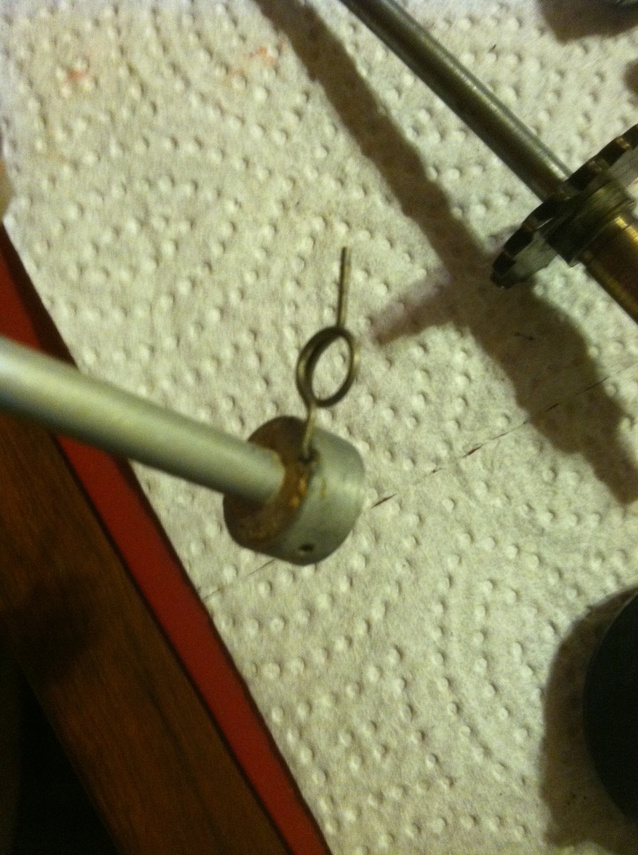
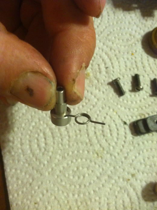
The anti-reverse eccentric spring for Spin fishers has the same asssembly, with reguards to Dog spring placement. Here it is shown on a 550SS. however unlike the 650-6500SS and higher, the 550SS has a small insulator sleave that slides down the Eccentric and holds the spring in place.
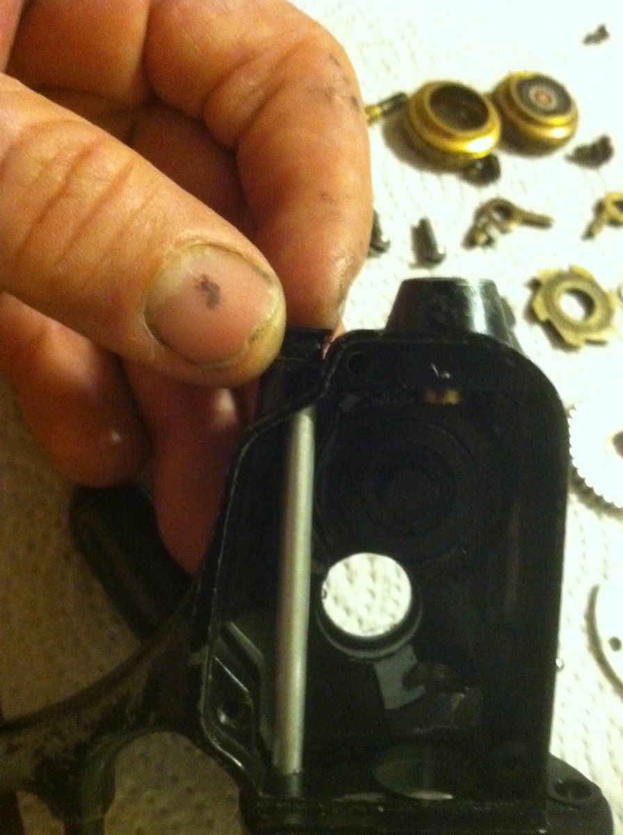
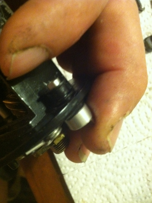
After sliding the Eccentric in from the rotor platform, guide the lower end through the base of the reel body and push the insulation liner or sleeve down up the shaft an into the gear casing. Then screw the Anti-Reverse lever, to secure it in place.
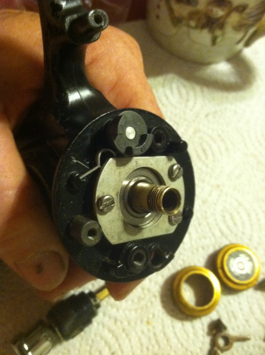
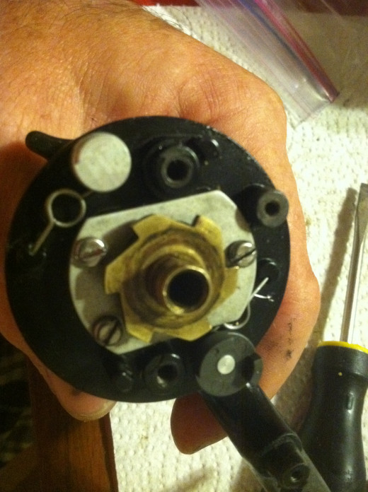
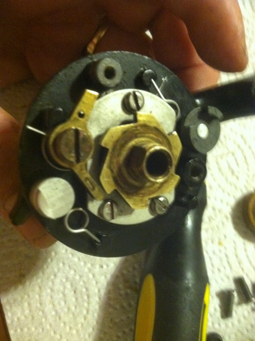
In this illustration, the Anti-Reverse Dog spring end is positioned into a small notch cast into the rotor table. Also the Pinion Gear and Bearing are installed along with the bearing cover. The reel should resemble this if it is assembled correctly. Now the "Silent Dog" shared by the larger Spin-fishers can be installed.
The Silent Dog Eccentric and Anti-Reverse Eccentric use the same Dog Spring and are installed the same way.
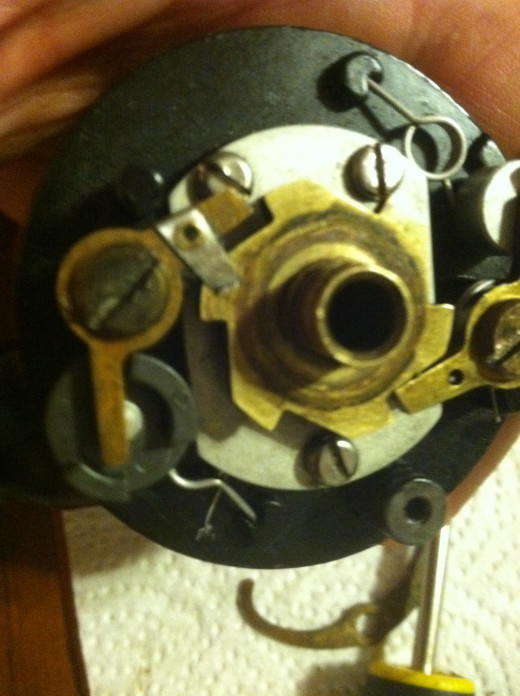
The Silent Eccentric is inserted trom the top of the Rotor Table, then the Eccentric Liner is pushed up the shaft from below and into the rotor paltform. Now the Silent dog Lever and trip bumper screw can be installed.
After installing the Anti-reverse Uper Eccentric shaft and Silent Eccentric shaft with the associated Dog Spring for each, the assembly should look like this
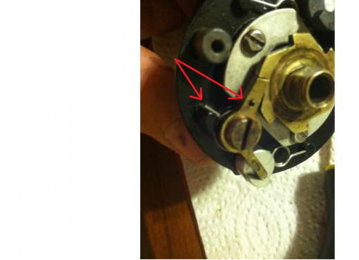
The Silent Dog, with the click dog spring can now be installed. Don't worry about setting the click dog spring until the dog screw is half way in. then the spring can be set by moving the strait portion of the spring towards the Dog, over the top of the spring stop until it is in position as pictured, and tighten the dog screw. Ensure before tightening the dog screw, that the Dog is slid over the pivot portion of the screw, or it can not be secured. When tight the dog should move freely. Apply a small drop of oil to the Dog and dog screw.
The Rotor Table should look similar at this stage of assembly.
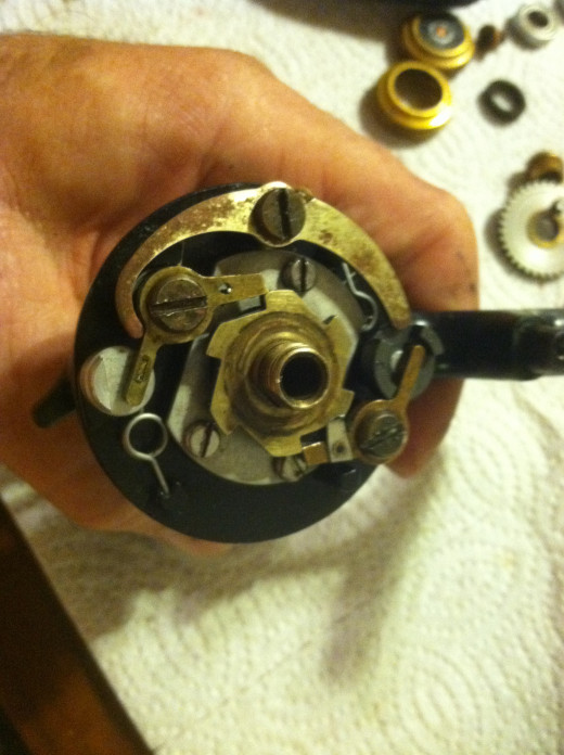
In this illustration the Anti-Reverse Dog is installed with the Anti-Reverse Gear riding on the pinion shaft. The Anti-Reverse gear is between the Dog fingers.
The Transfer lever is show in position. It also will need to be slid up the screw until it moves freely before tighteneing. The Rotor Table should be complete and resemble this illustration. The Rotor and Bail assembly can now be installed. Further instructions can be found on other hubs relating to the Spin Fishers here: http://must65gt.hubpages.com/hub/Penn-450SS-4500SS-550SS-and-5500SS-Cleaning-assembly Where the Main gear and crosswind assembly is discussed.


