IEC 61850 - How IEC61850 WORKS ?


Introduction to 61850 and Concepts :
Important Terms :
- Station Bus
- Process Bus
- Logical Nodes
- Self Description
- GOOSE messaging
- Client Servers
- Sampled Values
- SCL/XML
The goal of IEC 61850 is to define digital communications within a substation ( Protocols , Data types , Message formats etc ) . IEC 61850 is all about two concepts – How we know a piece of information and How we share this information . How to know a piece of information means that - what that particular piece of data actually represents, from where it comes from and can we trust this data . Sharing the information with other devices implemented the same protocol can be accomplished by the use of Publish/Subscribe model OR MMS model. These are the two main concepts of 61850 . Everything else describes how to make use of these concepts.
IEC 61850 concepts
(I) How to know a piece of information
- What the info represents ( eg : Phase currents )
- Where it Comes from ( eg : Feeder name , number )
- Can we trust this information
(II) How to share that piece of information
- Publish / Subscribe model
- MMS model
Basically IEC 61850 is not a protocol , instead it uses protocols to accomplish its task . The standard 61850 book is having over 1200 pages with 10 parts . It is referred by other standards and also dependent on other standards . Long term vision is Inter operable devices – Devices which are able to communicate and connect to each other . But the protection functions, usual logic configurations etc are not going to be defined by IEC 61850 . That means the devices will be Inter operable not inter changeable.
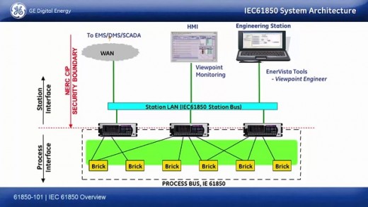
IEC 61850 System Architecture :
PARTS of IEC 61850 :
- Basic principles
- Glossary
- General Requirements
- System & Project Management
- Communication Requirements
- Substation automation system configuration
- Basic communications structure ( 4 sections )
- Mapping to MMI & Ethernet
- Sampled measured values and mapping to Ethernet
- Conformance testing
Communication Interfaces :

The 61850 standard defines different communication interfaces at the different levels of the substation . There are 3 types of communication interfaces in a substation and they are – Station level Interfaces , Bay / unit level Interfaces & Process level Interfaces .
Communication Interfaces :
(I) Station Level Interfaces
(II) Bay/Unit Level Interfaces
(III) Process Level Interfaces
- Station Level Interfaces :- Communication interfaces between station level devices ( like Gate ways , Automation controllers , Interlocking logic etc ) up to the wired system outside the substation and into the bay devices .
- Bay/Unit Level Interfaces :- Communication interfaces between bay level devices ( like Relays , Bay control units , Meters , Protection and control devices) in the same bay and between bay level devices of different bays .
- Process level Interfaces : Communication interfaces of primary level equipments ( like CTs, VTs, Breakers etc ) and the status control of these equipments .
Station Bus & Process Bus are two common usage words in the industry which are intended to help us understand basic application concepts . Station Bus normally defines all the communications at the Bay level ( between devices @ bay level & between different bays @ bay level) and between the Station level equipments ( Gateways , Automatic controllers etc ) . Communications at all these levels are collectively known as Station Bus. Interface 4 & 5 between the Bay level devices and the primary process level equipments is known as Process Bus .

System Communication Requirements :
Let us consider an example of a Double bus single breaker line bay . In each bay there are two groups of information are there and each of them is having its own specific requirements .
Protection Information :
- We need measured currents and voltages for the Protection functions , Tripping , Reclosing , blocking , Status information etc
- Requires high Reliability , Low Latency of communications , Deterministic properties
Operations Information :
- Reporting , Control Interlocking
- Requires verified and trusted information
The first challenge in using 61850 is that it does not distinguish between Protection and Operation information. Meeting the performance requirements for protection and operation over the same network using same devices brings the first challenge in implementing 61850 .
How 61850 works ?
(I). Functional Modeling of the Power System : - Functional modeling of the power system means that I can break a substation into a group of compounded functions . These functions may be like Instantaneous OC protection OR reclosing OR isolator switch control etc.
(II). Self Description of Information : - When the data is send, it is possible to put a description of the data in to the message ( eg : R phase current of Feeder 01 etc)
(III). Application Based Transmission :
i. Publish – Subscribe for “ RIGHT-NOW “ data
ii. Client – Server for “ MUST-TRUST ” data
(IV). XML for configuration and documentation :
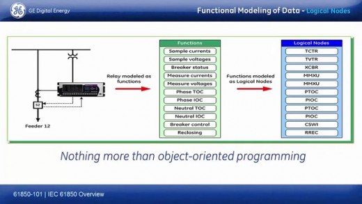
(I) Functional Modeling of Data :
Logical Node Expansion:

Consider the following example of a feeder relay which protects a line feeder . The relay measures the currents and voltages of the bus , currents from the line , knows the status of the breaker and controls the breaker .The functions a feeder relay can perform are – It samples currents , samples voltages , knows breaker status , measures currents , measures voltages , phase and neutral protection functions , breaker control , reclosing etc. Once these functions are defined , these functions can be modeled as logical nodes .
A Logical Node is an abstract model of a real device or function. The model includes Data , Data attributes & Behavior.
Eg : MMXU – Measurement ; XCBR – Circuit Breaker ; RSYN – Protection Related ; YPTR - Transformer
There are different information categories in Logical nodes which are Common Logical node information, Status Information , Settings Information , Measured Values Information , Controls Information .
Expansion of the MMXU Logical Node :
Logical Node = Descriptive Prefix +LNinstance number +Fn.Constraint+DataItems+DataClass
Eg : aaa MMXU xx
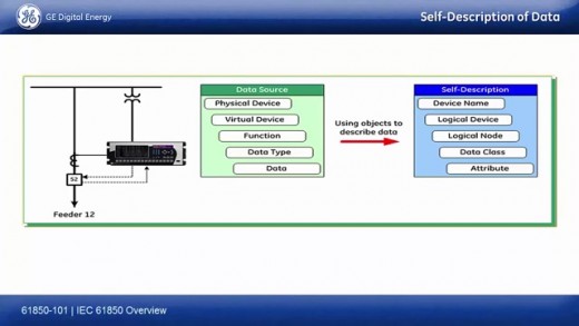
(II) Self Description of Data :
Anatomy of Object Names:
Self description of data is one of the major advantage of 61850 over other protocols such as DMP , 103/104 etc . The above mentioned protocols are register based protocols . That means for a particular piece of information we will get to know only the value of that information, but we will not be able to know what that information really represents. In 61850,the data source sends the data along with the device details ( eg : from which relay the data is coming from ) , detail of the function it represents and the type of data . It uses objects to describe the data . So in the self description method , Device name , Logical device , Logical code , Data class & Attributes are send with the data.
Consider these examples to understand how the data is send in ‘Self Description method’:
- Feeder12.LD3.MMXU.MX.A.phasA
Feeder 12 - Device Location
LD3 - Subset of device, LD3 for Metering
MMXU - Logical node, Measurement
MX - Data class, Measurement
A - Data attribute , Current
phasA - Data attribute , Phase A current
- Feeder12.LD6.XCBR.ST.Pos
Feeder 12 - Device Location
LD6 - Subset of device, LD6 for Control
XCBR - Logical node, Breaker control
ST - Data attribute, Status
Pos - Data attribute, Position
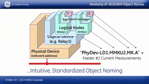
Anatomy of 61850 Object Names :
Now we will take a look at the 61850 Object names and how they are defined .An object name consists of Network address , Logical Device , Logical Nodes , Functional Constraints ( Type of Data coming out of it ) and the Type of Data.
Physical Device . Logical Device . Logical Nodes . Functional Constraints . Type of Data
Network address Eg : Relay 1 Eg : MMXU1 Eg : MX Eg : V , A
MMXU2 (Type of Data)
Eg : Phy Dev - LD1. MMXU2. MX. A
(III) Application Based Transmission :
a) Publish-Subscribe (Multicast) Model - For Protection Purposes ( “RIGHT-NOW” data )
b) Client-Sever Model - For Operation Purposes ( “MUST-TRUST”data )
(a) Publish-Subscribe (Multicast Model) :
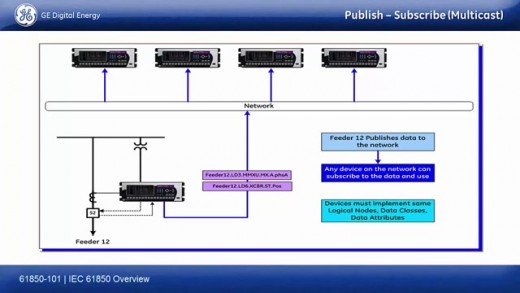
One of the protocols 61850 uses is the basic ETHERNET protocol to transmit the data . Publish-Subscribe is a Multicast way of sending the data . This model is simple , fast and suitable for sending the RIGHT NOW data .
Eg : Consider an example in which a feeder relay of Feeder#12 has to send Phase A current & Status of the Circuit Breaker to the network . Other devices need this piece of data . In old days we used to connect the Relay to an RTU or GATEWAY to get the data out . But in 61850, we can publish this data to the network and any device in the network can subscribe and can use this data .
The device requirements for this model is that , all the devices which has to subscribe the data must implement the same Logical nodes , Data classes and Data attributes to subscribe and use this data.
The following data types uses Publish-Subscribe model for sending data .
- Peer to Peer messaging ( GOOSE )
- Instantaneous Sampled Values
- Reporting ( Metering data for SCADA )
(b) Client-Server Model :
The Client Server model is used for the “Must Trust” data transmission and is used for the Operation purposes. The main difference between the MMS model and the GOOSE messaging (Publish – Subscribe model ) is that , in the MMS model once the data is send there will be an acknowledgement that the date is received . The data will be resend only if the acknowledgement is not received. But in the GOOSE messaging there will not be any acknowledgement for the data , and will keep on sending the data for a time period at specific time intervals . This is the reason why the ‘Publish Subscribe model’ is suitable for the Protection purposes and ‘the MMS model’ is for Operation purposes.
One of the communication interfaces 61850 defines is the ‘Abstract Communication Service Interface ‘ ACSI ’ which is the common interface for trust and verify data and it is mapped together with MMS services for better results . The goal of the MMS service is Trust & Verification .
(IV) XML for Configuration & Documentation :
IEC 61850 defines a common description language configuring 61850 communications in all IEDs and is known as Substation Configuration Language SCL . SCL is an XML based language that allows a formal description of substation automation system & the switch yard and the relationship between them .
Advantages of IEC 61850 :
- Possible to commission in the lab / factory before shipping to the site
- Repeatability – Design , Commission & Install the same system over and over again
- Significant cost savings (Less control wiring )
- High Degree of Flexibility
")

