Magnetohydrodynamic (MHD) Propulsion Boat - Research Methodology
This is Chapter 2 of the investigatory project entitled "Speed of a Magnetohydrodynamic Propulsion Boat as a Function of Salt Concentration" submitted to Science and Mathematics Education Department (SMED) of University of San Carlos. This lays down the magnet holder construction, channel width optimization, construction of the MHD boat, and research set-up of the study.
You may need to read the other chapters to see the study as a whole. Below are the links:
MAGNET HOLDER CONSTRUCTION
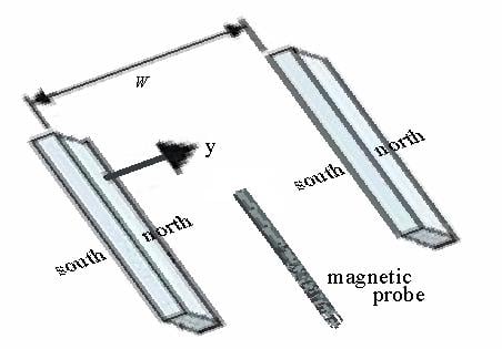
- Two (2) pieces of Styrofoam®, each with length of 17.00 cm, width of 2.80 cm and thickness of 1.80 cm, were cut. These served as the holders for the magnet as well as the sides of the channel.
- The shape of one array of magnets was carved on one side of one piece of Styrofoam® and the other array on the other Styrofoam®. It was carved in a way that the magnets were snugly fit.
- The depth of the carving was as deep as the thickness of the magnets. This way, when the magnets were put in place, it doesn't protrude out of the hole even if their ends repel each other.
- Two (2) rulers were cut into pieces with a length of 17.00 cm and a width of 2.80 cm. These were used to hold the magnets in place. This also served as the immediate side of the channel, minimizing the magnets' exposure to the salt solution.
- The magnets were then placed in their Styrofoam® holders, with the north pole facing outward on one, and the south pole facing outward on the other.
- The rulers were placed over the magnets to secure them in place. The rulers in turn were secured to the Styrofoam® holder by means of masking tape wound around them.
CHANNEL WIDTH OPTIMIZATION
- A teslameter was used to take measurements of the magnetic field strength between the magnets positioned side by side.
The magnets, already secured inside their holders, were separated using rulers whose individual widths were 1 mm.
- The first separation distance (W) was 7 mm, and including including the width of the rulers on the holders, this was achieved by inserting five rulers between them. The measurements were done at distance of 2 mm, 4 mm and 6 mm from the north pole of one of the magnets. This was done by removing the first, third and fifth separator ruler, respectively, and placing the axial probe of the teslameter in its place. (The thickness of the probe was less than 1 mm.)
- The second separation distance (W) was 11 mm, and including the width of the rulers on the holders, this was achieved by inserting nine rulers between them. The measurements were done at distance of 2 mm, 4 mm, 6 mm, 8 mm and 10 mm from the north pole of one of the magnets. This was done by removing the first, third, fifth, seventh and ninth separator ruler, respectively, and placing the axial probe of the teslameter in its place.
- The third separation distance (W) was 15 mm, and including the width of the rulers on the holders, this was achieved by inserting 13 rulers between them. The measurements were done at distance of 2 mm, 4 mm, 6 mm, 8 mm, 10 mm, 12 mm and 14 mm from the north pole of one of the magnets. This was done by removing the first, third, fifth, seventh, ninth, 11th and 13th separator ruler, respectively, and placing the axial probe of the teslameter in its place.
- The fourth separation distance (W) was 19 mm, and including the width of the rulers on the holders, this was achieved by inserting 17 rulers between them. The measurements were done at distance of 2 mm, 4 mm, 6 mm, 8 mm, 10 mm, 12 mm, 14 mm, 16 mm and 18 mm from the north pole of one of the magnets. This was done by removing the first, third, fifth, seventh, ninth, 11th, 13th, 15th and 17th separator ruler, respectively, and placing the axial probe of the teslameter in its place.
- The data gathered from the measurements were summarized in Table 1.
- Using Microsoft Excel 2003, the magnetic field strength values were graphically displayed as the magnet separation was increased.
- The average magnetic field as a function of the distance between the magnets was determined by curve-fitting and integrating the results.
- The magnetic fields were given in teslas and the separation in meters in order to allow substitution for the magnetic field strength (B) directly into equation 8 (see Theoretical Background for the derivation):
- The curve fit for the results of no. 8 were inserted to the above equation in order to yield an empirical force function of F that is proportional to a function of W.
- The resultant function F versus magnet separation W was graphically shown.This was done by choosing arbitrary points for the values of the Vbattery, and ρ, substituting these to the equation, and substituting values for W to get corresponding F. Vbattery used was 70 volts, equal to the resultant voltage output of the nine 9-volt batteries in series used as the voltage source for the boat. Actual Vbattery was measured using a voltmeter. The resistivity used was the same as the resistivity of sea (salt) water of 0.22 Ωm. The value of was the water channel length (17.00 cm).
- From the graph, the optimum separation width between the magnets was determined. This can also be done by applying the first derivative on the equation.

CONSTRUCTION OF THE MHD BOAT
- The size of the boat was chosen such that it was large enough to float the boat with the battery stack, composed of nine 9-volt batteries connected in series, placed on it. The hull of the boat was made up of Styrofoam®.
- The water channel length () was as long as the boat, approximately equal to the length of the magnet holders (17.00 cm).
- The channel height (H) was chosen to match the height of available magnets plus the thickness of the electrodes (2.80 cm).
- The channel width (w) was given by the process of optimization, as derived in the previous section of this methodology (found to be 1.98 cm, as shown in the next chapter).
- The water channel was constructed using the dimensions specified in nos. 2 to 4. Brass strips 17.00 cm long and 1.76 cm wide were used as electrodes, and were placed at the top and bottom of the channel. The electrodes were secured using pieces of rulers.
- Three (3) pieces of Styrofoam® (17.00 cm by 17.00 cm) were cut and held together on top of each other by means of the double-sided tape. This served as the hull of the boat.
- A gap 17.00 cm long, 5.96 cm wide and 2.80 cm deep was carved on the underside of the stacked Styrofoam®.
- The channel was then inserted and secured inside the gap.
- The battery stack was laid on the hull.
- Heavy-gauge connecting cables were used to connect the top electrode to the positive terminal and the bottom electrode to the negative terminal of the battery stack.
- The flag was placed near the front of the boat. In this case, a marker pen was used as the flag. Its width was measured using a Vernier caliper and was then recorded.
RESEARCH SET-UP
- A glass aquarium (with the dimensions 60 cm × 120 cm, height 50 cm) was used for this experiment. The size of the aquarium was chosen such that there would be lesser chance for the boat to hit the sides of the tub. Also, a wider aquarium would make the propagation of ripples to die out faster, allowing the boat to stabilize better.
- The aquarium was filled with 14 liters of distilled water, sufficient to float the boat. The water was measured using a volumetric flask.
- Using a compass, the direction of the magnetic north pole was determined. The aquarium was positioned perpendicular to this direction. This was to align the magnetic polarity of the boat with the magnetic field of the earth to prevent it from swiveling and changing directions.
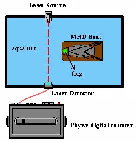
- A laser source was positioned on one side of the aquarium. A laser sensor/detector was positioned on the other side. The laser source and sensor were situated well above the surface of the water, but not over the height of the boat's flag.The light sensor was connected to the Phywe digital counter. The timer was set to the timer function and at the last trigger. This configuration allowed the timer to start when the laser was intercepted and to stop when the laser signal was resumed.
Approximately 1.5 kilogram of laboratory-grade sodium chloride was dissolved in the water. The exact mass was measured using a weighing scale. It was stirred thoroughly to ensure that it was completely dissolved. The concentration of the solution was calculated by dividing the mass of dissolved salt by the volume of the distilled water (14 liters).
- The MHD boat was placed on one end of the aquarium. The batteries were not yet connected at this point (this was done by unclipping the connecting cable from the positive terminal). The boat was allowed to rotate until it was stable to make sure that it was aligned with the earth's magnetic field.
- Once the boat had stabilized, the circuit was closed allowing the current to flow. The boat was placed with its flag approximately 5 cm from the laser beam. This distance was chosen so that the boat would only need to travel a short distance at every trial. That way, the energy of the battery was conserved. The distance was also chosen to allow it to presumably reach its terminal velocity.
- After the timer was triggered and stopped, the time displayed on the digital counter was recorded.
- Procedures 7 to 9 were repeated twice to get a total of three trials. (There were only three trials because having too many would drain the battery stack and corrode the electrodes fast.)
- The salt solution was then thrown away. The electrodes were cleaned using sandpaper. The aquarium was cleaned thoroughly, and 14 liters of distilled water was added. Approximately two (2) kilograms of laboratory-grade sodium chloride was dissolved in the water. The exact mass was measured using a weighing scale. It was stirred thoroughly to ensure that it was completely dissolve. The concentration of the solution was calculated by dividing the mass of dissolved salt by the volume of the distilled water (14 liters). Procedures 7 to 10 were repeated.
- Procedure 11 was repeated for 2.5, 3.0 and 3.5 kilograms of sodium chloride dissolved in water..
- The speed of the boat was calculated by dividing the distance d by the time it took for the boat to travel across. The average speed of the boat at every concentration was calculated.
- All data gathered was summarized in Table 2.
- Using Microsoft Excel 2003, the speed of the boat was graphically displayed as the salt concentration was increased.


