What is Yagi-Uda Antenna

Names and History
The Yagi antenna or Yagi-Uda RF antenna is widely used where directivity and gain are required from an RF antenna design. It is also one of the most successful or widely used RF antenna designs for directive applications. Yagi-Uda antenna is its full name, it is commonly known simply as Yagi or Yagi antenna. It is also called as the ‘beam antenna’. RF stands for radio frequency. This antenna derives its name from two Japanese inventors Yagi and Uda (his student). There are many different types of antenna and each type is suited to a diferent purpose and works best at particular frequency.
The Yagi can be used for receiving or transmitting radio signals. These antennas were widely used in World War 2 because they were simple to build and directional. Since Yagi antenna is directional therefore it is different from a standard dipole antenna which picks up signals equally well in any directions. The simplest form of antenna is the dipole antenna, it uses one piece of wire or a single element.
Yagi Antenna

How to Use Yagi Antenna
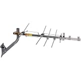
Each Yagi antenna consists of dipoles, reflectors and directors. The main part which holds the elements of the Yagi antenna is called the crossbar or boom. You need to point the crossbar or boom towards the direction of the signal you want to receive. If you notice all the television antenna on top of a group of houses, you will realize that all of the antenna’s crossbars are pointing in the same direction. That will tell you the direction in which the television transmitter is located.
Yagi Antenna Diagram

Parts of Yagi Antenna
A typical Yagi might have a gain figure around 3 – 20 dBd. Yagi antenna’s directionality can be measured in terms of its gain. The antenna is composed of several different parts. There is a dipole that is connected to the coaxial cable. The dipole is the driven element of this Yagi antenna, it receives radio frequency energy in a circular fieldd ending at the center of the dipole. There are also several parasitic elements which are not connected to the cabling. Those extra parts are a reflector and at least one director. Behind the dipole, there is a reflector which is usually 5% longer than the dipole. Reflector is used to reflect any signal that goes past the center element. And the directors are progressively shorter (approximately 5%) than the driven element (dipole). Directors are used to direct the direction the signal needs to go. With this Yagi antenna, every part of the antenna normally lay on the same plane.
Other types of antenna

How Yagi Antenna Works
It is known that the addition of further directors increases the antenna’s directivity, the gain and reduces the beamwidth. But the addition of further reflectors makes no difference. More dipoles the antenna has on the same plane, the more bands of signal it can pick up at the same time. In some Yagi antennas, the director is cut too short and therefore it has to be carefully placed aruond one wavelength away in order for it to rremain useful to the antenna. When you point the Yagi in the direction of the signal, the smaller elements pull the signal into the middle element, and then the longer elements will reflect back any signal that wuold be lost back to the center element.
This type of antenna is made to focus in one direction, forward. Waves in other direction are canceled out. Yagi antenna uses a technique known as beamforming for signal receiving and/or transmitting. Beamforming takes the signal and guides the direction that it goes. In fact, the Yagi is the most commonly used antena in application that operate above 10 MHz.


