Automatic, Instant Start Car Wiper Delay Timer Circuit

A wiper delay is essentially a bistable multivibrator whose off-time is adjustable with a potentiometer.
Many wiper delay circuits are based on the type 555 timer in its standard application circuit, which has the disadvantage of introducing a delay of about 1.6 times the set interval before the first wiper action takes place.
This is especially annoying when an interval of, say ten or more seconds has been set. This circuit is also 555 based, but is unique in that it arranges for the wipers to be activated immediately at power-on.
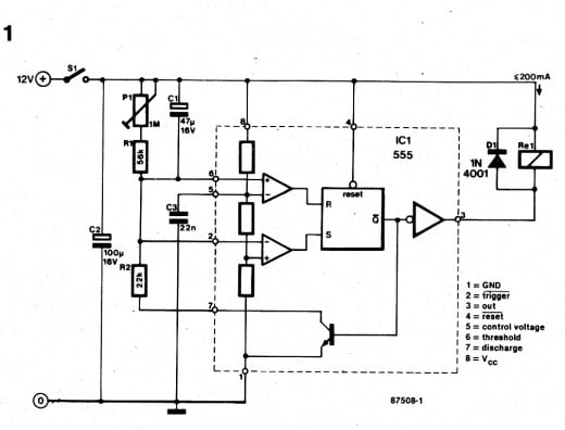
The circuit diagram shows the internal organization of the 555 timer to aid in clarifying the operation of the present circuit. When S1 is closed, pin 6 is immediately pulled to +12 V because C1 is discharged as yet.
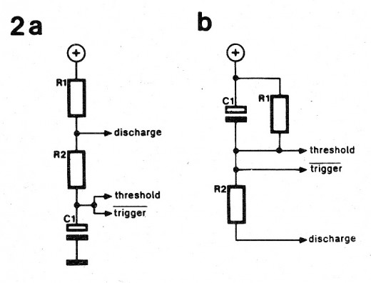
The bistable in the 555 is reset, the output goes low, and Re1 is energized. This forms the basic difference with the standard application of the 555, where C1, connected as shown in Fig. 2a, delays the relay action until charged to % of the supply voltage.
Returning to Fig. 1, C1 is charged via R2 and the 555’s internal transistor when the output is activated. The bistable is reset when the voltage at pin 2 drops below 1/3Vcc, causing the relay to be de-energized, and C1 to be discharged via R1-P1.
The discharge time, and hence the wipe interval, is defined by the setting of P1. When this is set to the shortest delay, the wiper motor is constantly powered via Re1, since C1 is not charged via P1-R2 only but effectively via voltage divider P1-R1-Rz also. The wiper delay is fed from the 12 V car battery, and its current consumption is practically that of the relay alone. Note that the coil current may not exceed 200 mA.

")
