Maintenance Program for Medical Facilities : Part II- Emergency Management Program (In case of utilities failure)
PART II - EMERGENCY MANAGEMENT PROGRAM- IN CASE OF
UTILITIES FAILURE
Purpose:
To establish an Emergency Management Program designed to provide operational reliability and quick response to the failure of utilities that support the patient care environment.
Objectives
The risk management of the utility systems will be controlled by a program of testing and maintenance of the systems, and the training of personnel in problem resolution. The standard for this program is zero ( 0 ) occurrence of serious injury or death to a patient or staff member resulting from failure or malfunction of defined critical utility systems. This document will address the following issues:
Goals:
A. To identify critical utilities that play a role in operating life support, infection control, support and communications systems.
B. The adherence of the medical facilities to relevant building codes and required standard of maintenance and operation of utility systems.
C. To maintain a current inventory of all utility systems and accurate maintenance records.
D. To provide a manual outlining the program of training which all maintenance staff shall be required to attain. Records of training of each staff shall be maintained in this manual.
E. To retain a current, accurate set of documents indicating the location of controls for partial or complete shutdown of each utility system. Emergency shut-off controls must be adequately labeled.
F. To provide a written utility system operational manual, to insure reliability, control risks, reduce failures, and train users and operators of the system. The operational manual will include plans for the management of failure and emergency procedures.
G. To maintain a record to identify and document utility problems, failures, and user error that are, or may be, a threat to the successful operation of the environment of care.
H. To maintain a record to document regular water supply testing results.
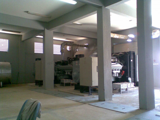
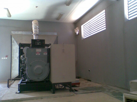
I. Back-up / emergency power generator systems will be tested monthly as per Joint Commission on Health Care Organization (JCIAHO) and Joint Commission International Accreditation (JCIA) requirements.
J. All staff should be aware that if , after 15 seconds, there is no back-up or emergency power, then all power systems have failed.
K. Back-up operational plans are maintained as current for all critical utility systems.
SECTION 1 - Plan on what to do in case of failure, or interruption of the following utilities:
· Normal Power
· Emergency Power, and Cases of: No Power in Socket Outlets
At Critical Areas, and Lamp Failure at Critical Areas
· Elevator
· Water Supply
· Water Treatment (Reverse Osmosis) Plant
· Air Conditioning Unit at Patient Room
· Air Conditioning Unit Including Air Handling Unit at OR's
· Medical Gas System
· Sewer Lines
· Boiler
· Telephone Service (PABX)
· Intercom, Nurse Call or Overhead Paging
· Fire Alarm Problems
1.1 - Failure of Normal Power
A. In the event of normal power failure the work clerk shall notify the Hospital Manager at EXT 2000, the Maintenance Manager, the Generator's Engineer and the Electrical Engineer
B. The Generator's Engineer shall make sure the essential power generators allowed entrance to the service and the Electrical Engineer shall dispatch technicians to the main distribution panels.
C. The Technicians shall carry out the following procedures and report the status to the Electrical Engineer:-
1- Check generator operation and fuel level.
2- Check the adequate emergency power is available at:
· Ward areas.
· Critical care areas.
· OR's
· LAB
3- Assess the nature of the normal power failure.
D. The Electrical Engineer shall initiate appropriate corrective action by one or more of the following:-
1- Initiate repairs.
2- Inform the maintenance manager about the status.
3- Call the Power Utility Company if needed.
1. 2 - Failure of Emergency Power Supply in the Presence of Normal Power
A. The generator's Engineer shall notify the work clerk at Ext 2269.
B. The work clerk shall notify the Hospital Manager at EXT 2000 and the Maintenance Manager.
C. The Maintenance Manager shall notify the electricity company about the situation in order to ensure uninterrupted power supply.
D. The generator's Engineer shall dispatch the technicians to check the emergency power systems.
E. The Technicians shall carry out the following checks on the emergency power and report the status to the generator's Engineer:-
1- Check the generator operation and control panel.
2- Check the Automatic Transfer Switches ( ATS).
3- Check the distribution panels.
F. The generator's Engineer shall initiate appropriate corrective action by one or more of the following:-
1- Initiate repairs.
2- Inform the maintenance manager about the technicians report.
3- Call the Agent if necessary.
1. 3 - Failure of Emergency Power Supply in the Absence of Normal Power
A. The generator's Engineer shall notify the work clerk at Ext 2269.
B. The work clerk shall notify the Hospital Manager at EXT 2000 and the Maintenance Manager.
C. The Maintenance Manager shall notify the Power Utility Company (if possible ) to restore power immediately to the hospital due to problems with the Emergency power generators.
D. The generator's Engineer shall dispatch the technicians to check the emergency power systems and ATS panels
E. The Technicians shall carry out the following checks on the emergency power and report the status to the generator's Engineer:-
1. Check the generator operation and control panel.
2. Check the Automatic Transfer Switches ( ATS).
3. Check the distribution panels.
F. The generator's Engineer shall initiate appropriate corrective action by one or more of the
following:
1. Initiate repairs
2. Inform the maintenance manager about the technicians report
3. Call the Agent if necessary.
1. 4 - Failure of Emergency Power, Cases of: No Power at Socket Outlets at Critical Areas And Lamp Failure at Critical Areas
A- The Nursing Station will notify the work clerk at Ext 2269.
B- The work clerk shall notify the Electrical Engineer.
C- The Electrical Engineer shall dispatch the technicians to investigate and report the cause of the problem as follows:-
1- Check the room number.
2- Go to nearest electrical room.
3- Open the panel and check the room number.
4- Switch on the breaker or trouble shoot as necessary.
1. 5 - Elevator Failure
A. Reporting the problem
1. In the event of the elevator being stuck without passengers, the affected department should notify the work clerk at Ext 2269.
2. The passengers in the elevator shall use the intercom to notify the control desk at the
elevator's department and which should notify the work clerk at Ext 2269.
3. The work clerk shall notify the Electrical Engineer of the problem.
B. The Electrical Engineer will dispatch the technicians to check the cause of the problem and their priority shall be to release any trapped passengers in the elevator, then switch off the elevator and put a sign stating that ( elevator is out of service – under maintenance ) at each floor.
C. The Electrical Engineer based on the technicians report shall initiate one or both of the following actions:-
1. Initiate repair procedures.
2. Call the Agent if necessary.
1. 6 - Failure of Water Supply
TOTAL OR ISOLATED LOSS OF WATER SUPPLY
A- Reporting the problem:
1- By water plant operator.
2- By the affected Department.
B- The work clerk shall notify the Hospital Manager at EXT 2000, the Maintenance Manager and the Mechanical Engineer .
C- The Mechanical Engineer shall dispatch the technicians to investigate and report the cause of the failure internal or external and do the following:-
1- In case of pipe line leakage
· Isolate the defective line by closing the valve.
· Inform the affected area.
2- Malfunction of domestic pump
· Switch off the defective pump.
· Ensure automatic start of the other stand-by pump. If not, DO IT MANUALLY.
3- Shortage of water supply
· Immediately call the water supply subcontractor for the needed quantity of water.
D- The Mechanical Engineer based on the report of the technicians shall initiate appropriate corrective action by the following:-
1- Initiate repair procedures.
1. 7 - Failure of the Reverse Osmosis Plant
A. The Reverse Osmosis operator on duty in the event of failure in the RO plant product water supply, shall notify the work clerk at Ext 2269 and identify the nature of the failure.
B. The Reverse Osmosis operator on duty shall switch of the defective parts or all the plant if it necessary.
C. The work clerk shall notify the Mechanical Engineer and Maintenance Manager .
D. The Mechanical Engineer shall notify the affected departments.
E. The Mechanical Engineer shall dispatch the technicians to investigate and report the cause of the failure.
F. The Mechanical Engineer based on the information reported by the technicians shall initiate the corrective action by one or more of the following:-
1- Initiate repair procedures.
2- Inform the Maintenance Manager to call the Agent if necessary.
1. 8 - Failure of Air Conditioning Unit at Patient Room
Window or Split Type Air Conditioning Unit
A- The Nursing Station will notify the work clerk at Ext 2269.
B- The work clerk shall notify The Mechanical Engineer.
C- The Mechanical Engineer shall dispatch the technicians to investigate and report the cause of the problem.
D- The Mechanical Engineer based on the report of the technicians shall initiate appropriate corrective action by the following:-
1- Initiate repair procedures.
1. 9 - Failure of Air Conditioning Unit (Including Air Handling Unit) at
O.R.'s
Package Type/ Central Air Conditioning Unit
A. Reporting the problem , the affected department shall notify the work clerk at Ext 2269.
B. The work clerk will then notify the Maintenance Manager and the Mechanical Engineer.
C. The Mechanical Engineer shall dispatch the technicians to investigate and report the causes of the failure.
D. The Technicians shall check the HVAC Units and report back to the Mechanical Engineer.
E. The Mechanical Engineer based on the report of the technicians shall initiate appropriate corrective action by the following:-
1-Initiate repair procedures.
1.10 - Failure of Medical Gas System
A- Reporting the problem , the affected department shall notify the work clerk at Ext 2269.
B- The work clerk shall notify the Hospital Manager at EXT 2000, the Maintenance Manager , the Mechanical Engineer and the medical staff at the affected department.
C- The Mechanical Engineer shall dispatch the technicians to investigate and report the cause of the failure as follows:
1- In case of Pipeline leakage
· Isolate the line from the isolation valve
2- In case of Medical air compressor, medical vacuum pump failure
· Switch off compressor or pump.
· Start the stand by compressor or pump.
D- The Mechanical Engineer based on the report of the technicians shall initiate appropriate corrective action by the following:-
1- Initiate repair procedures.
2- Inform the Maintenance Manager to call the Agent if necessary.
1.11 - Failure of Sewer Lines
A- In the event there is blockage or breakage in the sewer lines notify the work clerk at Ext 2269.
B- The work clerk shall notify the Mechanical Engineer.
C- The Mechanical Engineer will dispatch the technicians to investigate and report the cause of the blockage.
D- The Mechanical Engineer based on the report of the technicians shall initiate appropriate corrective action by the following:-
1- Initiate repair procedures.
1.12 - Failure of Boiler
A. In the event the steam boiler shows signs of malfunction, the boiler operator shall notify the work clerk at Ext 2269.
B. The work clerk shall notify the Mechanical Engineer.
C. The Mechanical Engineer will dispatch the technicians to investigate and report the cause of the problem in view of the technician on duty.
D. The Mechanical Engineer based on the report of the technicians shall initiate appropriate corrective action by the following:-
1-Initiate repair procedures.
1.13 - Failure of Telephone Service (PABX)
A. In the event there is a sign of malfunction of the Telephone Service, the Telephone Operator will notify the work clerk at Ext 2269.
B. The work clerk shall notify The Electrical Engineer .
C. The Electrical Engineer shall dispatch the technicians to investigate and report the cause of the problem.
D. The Electrical Engineer based on the report of the technicians shall initiate appropriate corrective action by the following:-
1- Initiate repair procedures.
1.14 - Failure of Intercom, Nurse Call or Overhead Paging
A. In the event there is a sign of malfunction or failure of the Intercom, Nurse Call, or Overhead Paging System, the Telephone Operator will notify the work clerk at Ext 2269.
B. The work clerk shall notify The Electrical Engineer .
C. The Electrical Engineer shall dispatch the technicians to investigate and report the cause of the problem.
D. The Electrical Engineer based on the report of the technicians shall initiate appropriate corrective action by the following:-
1- Initiate repair procedures.
1.15 - Fire Alarm Problem
A. In the event there is a sign of problem in the Fire Alarm System, the Telephone Operator will notify the work clerk at Ext 2269.
B. The work clerk shall notify The Electrical Engineer .
C. The Electrical Engineer shall dispatch the technicians to investigate and report the cause of the problem.
D. The Electrical Engineer based on the report of the technicians shall initiate appropriate corrective action by the following:-
1- Initiate repair procedures.
SECTION 2 - Emergency Plans are tested in simulation at least once a year, and test results are evaluated.
2.1 ATTACHMENTS:
· Emergency Plans simulation test results.
PART III - Written Policy On How To handle Various Types Of
Compressed Gases, which includes:
· Storing them in a well-ventilated area.
· Positioning them upright the wall or a stand and secured by a chain.
· Separating any flammables from oxidizing gases.
Purpose:
The purpose of this policy is to establish a guideline to be followed on the proper procedure for the safe use, handling, and storage of compressed gases used in the hospital.
Policy:
It is the policy of hospital that the proper procedure for the safe use, handling, and storage of compressed gases shall be strictly followed.
General Rules:
Proper storage of cylinders is essential. Proper procedure for safe storage of compressed gases are as follows:
· Store only in designated areas. Never place and leave on the floor.
· Store empty cylinders separately from full cylinders.
· Secure with chains, stands, brackets, or in a rack.
· Always secure in an upright position.
· Remove all regulators before storage.
· Store large cylinders with caps on.
· Gas cylinders should not be stored in exits or way out routes or blocking any equipment.
Special storage requirement is based on the total volume of compressed gases in an area.
Partially full compressed gas cylinders containing residual gases shall be considered as full and are subject to the same controls and storage conditions.
When in use, all cylinders must be equipped with an appropriate regulating device. Always use the proper regulator. Always make sure that the regulator and valve fittings are compatible. Never "adapt" regulators or connections that don't fit any types of tanks. Leak check all connections before use. When opening up the cylinder valve of high pressure tanks, open them SLOWLY to prevent possible problems due to high pressure. Always turn off the cylinder valve when tank is not in use, NOT just the regulator flowmeter valve.
Oxidizing gases should be stored separately from flammable gases. All cylinders containing flammable gases should be stored in a well-ventilated area. If the gas is flammable, flash points lower than room temperature compounded by high rates of flow present a danger of fire or explosion. Additional hazards of reactivity and toxicity of the gas, as well as asphyxiation, can be caused by high concentrations of even "harmless" gases such as nitrogen.
Use a hand truck to move cylinders. Cylinders should never be rolled or dragged. When moving large cylinders, they should be strapped to a properly designed wheeled cart to ensure stability. Only one cylinder should be handled (moved) at a time. Never carry cylinders by the valve stem, also, never carry them on your shoulder.
No compressed gas cylinder should be accepted for use that does not identify its contents by name.
The cylinder should be marked "contents unknown" and returned to Maintenance Department. Never count on the color of the cylinder for identification. The best way to determine what medical gas is in a tank, is to insure that each tank has a label on it describing the contents of the gas inside. If there is no label, Do Not Use.
Cylinders containing compressed gases and containers for volatile liquids shall be kept away from radiators, steam piping, and like sources of heat. These containers shall NOT be stored in a tightly closed space.
Definition of Terms:
Anesthetizing Location- Any area of a health care facility that has been designed to be used for the administration of any flammable inhalation anesthetic agent in the course of examination or treatment, including the use of such agents for relative analgesia.
Combustible Materials that could be found near patients- Include hair oils, oil based lubricants, skin lotions, facial tissues, clothing and linen, rubber and plastic articles, gas supply, suction tubing, alcohols and acetone. As much as possible avoid these in the area near where oxygen is being administered.
Compressed Gas – Any material or mixture, when in its container, having an absolute pressure exceeding 40 psia (an absolute pressure of 276 kPa ) at 70° F (21.1° C) or, regardless of the pressure at 70° F (21.1°C) having an absolute pressure exceeding 104 psia (an absolute pressure of 717 kPa) at 130° F (54.4°C).
Compressed Gas Cylinder- Any portable pressure vessel of 45.4 kg (100 lb) water capacity or less designed to contain a gas or liquid that is authorized for use at gauge pressures over 276 kPa (40 psi) at 21°C (70° F ) by the Department of Transportation.
‘E’ sized Compressed Gas Cylinder – Gas cylinder that holds approximately 25 cu.ft. of gas.
Flammable Anesthetics- Gases or vapors such as fluroxene, cyclopropane, divinyl ether, ethyl chloride, ethyl ether, and ethylene, which may form flammable or explosive mixtures with air, oxygen, or reducing gases such as nitrous oxide.
Flammable Compressed Gas- A compressed gas which forms a flammable mixture when 13 percent or less (by volume) is mixed with air, or a compressed gas having a flammable range with air wider than 12 percent, regardless of the lower limitation. These limitations shall be determined at atmospheric temperature and pressure. Flammable gases do not have flash points. Also: Any substance that exists in the gaseous state at normal atmospheric temperatures and pressure and is capable of being ignited and burned when mixed with the proper proportions of air, oxygen, and other oxidizers.
Flammable Material Storage Cabinet- A storage cabinet which is constructed in accordance with standards.
“H” sized Compressed Gas Cylinder - Gas cylinder that holds approximately 250 cu. ft. of gas.
Medical Air- Medical air is air supplied from cylinders, bulk containers, medical air compressors or has been reconstituted from oxygen USP and oil free nitrogen NF.
Oxidizing Gases- A gas that supports and accelerates combustion of other materials. Oxygen and nitrous oxide are examples. There are many others including halogens.
Upright Position- Position includes when compressed gas cylinders axis is inclined as much as 45 degrees from the vertical.
Responsibility:
Maintenance Department Management : Enforce this policy
Safety Department: Evaluate requests for use of non-refillable, non-returnable compressed gas cylinders.
Monitor the proper use storage and transport of compressed gas
cylinders during EMRs and other audits.
Safety Department And Respiratory Therapy: Provide formal education on safe storage of compressed gas cylinders
Educate personnel handling compressed gas cylinders.
All Staff: Store, transport and handle all compressed gas cylinders in accord with this policy.
Procedure:
1.The color of a compressed gas cylinder is not adequate identification of the contents of the cylinder.
A. The name of the gas must be on the cylinder (stencil or attached label) and this must be checked prior to using the gas for a patient.
B. Labels shall not be defaced, altered, or removed.
C. The expiration date must be checked prior to using the gas for a patient.
2. When in use for health care, all compressed gas cylinders must be equipped with an appropriate approved regulating device.
A. All regulators must be marked to identify the gas (or group of Compatible gases) with which the regulator is to be used.
B. Regulators are designed to fit only the threads of the compressed gas cylinder of one type of gas.
C. If the threads do not match the cylinder, do NOT use the cylinder until contents are determined by testing.
3. Because the hospital is a smoke free institution , because No Smoking signs are posted in the major entrances and because of strict enforcement of “No Smoking” policy , we are not required to post No Smoking signs at the actual location where oxygen is in use. There are other sign requirements listed in this policy.
4. Carbonated beverages cylinders are a type of compressed gas cylinder. Precautions listed below also apply to carbonated beverage cylinders.
5. Compressed Gas Cylinders must be secured to prevent falling caused by contact, vibration or seismic activity:
A. It is the policy of the hospital that all compressed gas cylinders, either in use or in storage (empty or full), shall be tightly secured by a strap, chain, non-tip base, within a rack or other approved means. The Safety Department needs to approve any other way of securing a compressed gas cylinder.
B. When securing the cylinders, one (1) is the highest number secured on a single chain/ strap as allowed.
C. When a compressed gas cylinder is being transported on a slanted carriage, it must still be secured by a strap, chain, or other approved means.
D. When a small – sized cylinders (A, B, D, or E) cylinders are use in , they shall be attached to a cylinder stand or to a therapy apparatus of sufficient size to render the entire assembly stable.
E. Cylinders shall not be chained to portable or movable apparatus such as beds.
6. Protective valve caps must be in place when “H” cylinders are not in use.
7. All cylinders must be equipped where necessary with a hand wheel, valve handle, spindle key, or a special tool to activate the cylinder valve. This shall be attached to the cylinder so that it will immediately be available in the event of an emergency.
8. Flammable compressed gases
A. Shall be grounded.
B. Shall be stored separately from oxidizing gases.
C. Must be stored in an approved storage area.
D. Flammable gas cylinders shall not be stored in a corridor, stairway or any means of egress.
E. Cylinders of liquefied flammable gas (i.e. Propane) are prohibited from use or storage inside any building .
9. All compressed gas cylinders must be returnable to the manufacturer for refill or proper disposal.
A. The use of commercially supplied gas in non-refillable, non-returnable cylinders is prohibited.
B. This restrictions eliminates unnecessary handling and disposal of compressed gas cylinders and their contents, and assures proper disposal of these materials.
C. Use of non- returnable compressed gas cylinders requires written approval by the Safety Department
10. Certain rules apply to all compressed gas cylinder storage regardless of the volume of compressed gases present.
A. Smoking , open flames, electric heating elements, and other sources of ignition shall be prohibited within storage locations and within 20 feet outside storage locations.
B. Storage of compressed gas cylinders will occur in such a way that they will be used in a first in / first out rotation.
C. Full and empty cylinders must be clearly identified as such:
1. If they are stored in the same area, empty cylinders should be separated from full cylinders. This is done in order to prevent delay in an emergency in determining whether tanks are full or empty.
2. Valves shall be closed on all empty compressed gas cylinders in storage.
D. Temperature in storage areas shall not exceed 125°F.
E. Storage areas shall not be near elevators, gangways, or in locations where compressed gas cylinders are likely to be hit or have something fall on them.
F. Compressed gas cylinders storage shall be secured against unauthorized entry.
1. If the storage area opens on a public hall this means the door(s) must be locked.
2. If it opens on a corridor which is not a public hall, it may not need to be locked.
G. Compressed gas cylinders shall not be exposed to corrosive chemicals or fumes.
H. All compressed gas cylinders must be stored and used in an upright position with the valve end up.
I. Only special compressed gas cylinders for use in a horizontal position can be placed in that position. The “E” Compressed gas cylinders are designed to used in the horizontal or vertical position.
J. Precautionary Signs which must be readable from a distance of 5 ft. shall be displayed on each door or gate of the storage room or enclosure (outside storage of compressed gases).
1. Storage locations containing medical gases other than oxygen and medical air shall have their door(s)labeled with a sign containing the following information.
CAUTION
MEDICAL (OXIDIZING) GASES STORED WITHIN
NO Smoking or Open Flame
Room may have Insufficient Oxygen
Open Door and Allow Room to Ventilate before Entering
2. Storage locations containing only oxygen or medical air shall have their doors labeled with a sign containing the following information.
CAUTION
Oxygen and Medical air Only
No Smoking or Open Flame
11. Storage conditions of Compressed Gas Cylinders is determined by the volume of compressed gases present in that specific location.
A. NFPA allows for up to a total volume of 300 cu.ft. of compressed (for example, oxygen) in an area (for example, a nursing unit) for immediate use. Once you exceed the 300 cu.ft., you have special storage requirements.
1. The average “E” sized compressed gas cylinder holds approximately 25 cu. ft. of gas, and simple division will show that 300/25=12. So 12 is the maximum number of “E” cylinders which can be stored without special storage requirements.
2. The average “H” sized cylinder contains approximately 250 cu.ft. of compressed gas. If you do not have special storage available, you can only have one “H” cylinder plus one or two “E” cylinders.
B. A compressed gas cylinder placed next to a patient’s bed and intended to be used within a short time would not be considered as being in storage.
C. Special storage for non-flammable gases with volume greater than 300 cu. ft. but less than 3000 cu .ft. have the following storage requirements:
1. Shall be within an enclosed interior space of noncombustible construction.
2. Cylinders containing oxidizing gases shall be stored separately from flammable gases or liquids.
3. Oxidizing gases shall be separated from combustibles or materials by one of the following :
a. A minimum distance of 20 ft.
b. A minimum distance of 5 ft. if the entire storage location is protected by an automatic sprinkler system designed in accordance with NFPA 13.
c. An enclosed cabinet of non-combustible construction having a minimum fire protection rating of ½ hour.
d. A wooden storage rack designed to secure compressed gas cylinders is expected from this requirement (i.e. it is not considered to be combustible).
D. Special storage for non-flammable gases with volume greater than 3000 cu.ft. (12”H” cylinders or 120 “E” cylinders) have the following storage requirements in addition to the requirements previously outlined in 11 C and 2.
1. A room dedicated to compressed gas storage or outside storage.
2. The storage locations for oxygen, nitrous oxide and mixtures of these gases shall be segregated from the following:
a. Anesthetizing locations
b. Areas involved in critical patient care
c. Locations storing flammables
d. Rooms containing open electrical contacts or transformer
e. Storage tanks for flammable or combustible liquids
f. Engines
g. Kitchens
h. Areas with open flames
3. Be easily accessible when cylinders have to be moved
4. Be heated by indirect means (e.g. steam, hot water) if heat is required.
5. Be provided with racks, chains, or other fastenings to individually secure all
cylinders, whether connected, unconnected, full, or empty, from falling.
6. Have racks, shelves, and supports where provided, constructed of non-combustible materials or limited-combustible materials.
7. Shall be vented to prevent the accumulation of medical gases from leaks and operations of cylinders. This storage area shall be provided with dedicated mechanical ventilation systems that draw air from within one(1) ft. of the floor and operate continuously. Venting systems for gas storage locations should not be interconnected with other facility air handling systems.
12. Use of compressed gas cylinders in construction carts and hand trucks being used for compressed gas cylinders shall be constructed for the intended purpose, be self – supporting and be provided with chains or strap to restrain the cylinders. Construction carts used in operating rooms need to be grounded.
13. Anesthesia in Operating Rooms.
A. If the sole source of supply of non-flammable medical gases, such as nitrous oxide and oxygen, is a system of cylinders attached directly to and supported by the device (anesthesia cart) used to administer these gases, it is recommended that two cylinders of each gas be attached to the administering device.
B. Anesthesia carts need to be grounded.
PART IV - Exhausts of the following gases are extended to the roof and identified:
- Lab safety cabinet gases of a certain class
- Central vacuum gases
- Anesthetic gases
Purpose:
To ensure the safety of all hospital staff, patients, and visitors from the harmful effects of lab safety cabinet gases of a certain class and central vacuum gases.
Policy:
It is the policy of the hospital that lab safety cabinet gases of a certain class, and central vacuum gases must have their exhaust confined in a closed vent, extended up to the roof outside of the building, where it is dispersed harmlessly to the atmosphere.
The discharge point shall not be located where affected by prevailing winds, adjacent buildings, topography, or other obstacles to the rapid dispersion of the exhaust gases.
This must be achieved during the design and construction of the medical vacuum and gas systems installation.
Procedure:
MEDICAL VACUUM AND GAS SYSTEMS
PART 1 – GENERAL
1.01 OVERVIEW
A. This section addresses medical vacuum, waste anesthetic gas disposal, compressed air, oxygen, nitrous oxide, nitrogen and carbon dioxide systems.
PART 2 - DESIGN CRITERIA
2.01 GENERAL
- Medical vacuum and gas systems shall be designed in accordance with current editions of AIA Guidelines for Design and Construction of Hospitals and Healthcare Facilities, NFPA 55, NFPA 99 and Compressed Gas Association Standards.
- Obtain all necessary information that is required from the Owner when determining system design and types of services.
- A proposed system design in either diagrammatic or narrative form shall be submitted to the designated Owner’s representative during the schematic phase of the Project.
- Review the location, quantity and type of medical gas outlets, inlets and alarm panels with Owner’s user groups during the design development phase of the Project.
- Medical vacuum and gas systems serving patients shall be independent of all other vacuum and gas systems serving laboratory, research and/or animal areas.
- Medical compressed air systems serving patients shall not be used to serve non-respiratory equipment, such as sterilizers, pneumatic doors, operating room service columns, etc.
- Design medical gas and vacuum systems to deliver the following nominal pressures at the points of use: All pressure systems, except nitrogen shall be 50 to 55 psig at maximum flow; Nitrogen shall be 160 to 185 psig at maximum flow; Vacuum shall be 15 to 19 inches Hg (380 to 482 mm Hg) at most distant inlets.
- Coordinate the requirement for the use of ventilators with the Owner’s user groups. Design the oxygen and medical air systems to accommodate required flow demands.
- Include waste anesthetic gas disposal (WAGD) terminal inlets and piping in appropriate projects. The source for WAGD inlets shall connect to the medical vacuum system piping above the ceiling and downstream of the zone valve box serving the individual room where the inlets are to be located.
- Provide at least one nitrogen control panel (NCP) within rooms containing nitrogen station outlets. Coordinate with Owner’s users to determine quantity and location.
- Locate station inlets and outlets at an appropriate height to prevent physical damage to attached equipment and accessories. Station inlets and outlets located above countertops shall be provided with sufficient space to allow usage and attachment of equipment without interferences by countertop, backsplash or overhead cabinets. All other station inlets and outlets having centerline located less than 60 inches above finished floor shall be protected by guardrails, recessing into walls or by other means approved by Owner.
- Provide sufficient spacing between station inlets and outlets to allow simultaneous use with vacuum collection bottles, regulators, adaptors or any other equipment attached. Provide slide retainer bracket for collection bottle attachment adjacent to each vacuum station inlet.
- Ensure that all medical vacuum and gas source equipment and alarm systems are provided with both normal and emergency electrical power supply.
2.02 CENTRAL SUPPLY SYSTEMS
A. Locate medical air compressors and vacuum pumps in a dedicated mechanical room in accordance with NFPA 99. Mechanical room shall provide a clean, relatively cool environment (i.e., not to exceed 100 degrees F ambient temperature). Equipment shall be located with adequate access space for regular monitoring and servicing. Provide floor drain adjacent to equipment pads. Floor drains serving vacuum pumps shall be provided with smooth, acid resistant interior coating. Provide a hose bib within mechanical room.
B. Locate the medical air compressor system intake outdoors above roof level, at least 25 feet (may require more depending upon prevailing wind direction and velocity) from all exhausts, vents, vacuum system discharges or any anticipated source of odor or particulate matter. Air that is filtered for breathable ventilation system use may be considered an acceptable source of intake air when approved by Owner’s representative. Combined air intakes must be sized for no restriction while flowing the maximum intake possible, and shall be provided with an isolation valve at the header for each compressor served. Intake piping for air compressors shall be sized using the total SCFM for the system (both lead and lag pumps) and the total developed length of run. Coordinate with air compressor system technical representative and verify that proposed sizing of intake piping complies with manufacturer’s recommendations.
C. Terminate medical vacuum exhaust discharge outdoors above roof level, at least 25 feet horizontally (may be more depending upon prevailing wind direction and velocity) from all air intakes, doors, windows, louvers or any other building openings. Combine exhaust from each medical vacuum pump into one discharge pipe, sized for no restriction while flowing maximum discharge possible, and shall be provide with an isolation valve at the header for each pump served. Exhaust piping for vacuum pumps shall be sized using the total SCFM for the system (both lead and lag pumps) and the total developed length of run. Exhaust piping shall be sized and arranged to prevent moisture and back-pressure from entering pump. Provide valved drip-leg at base of exhaust stacks. Coordinate with vacuum pump system technical representative and verify that proposed sizing of exhaust piping complies with manufacturer’s recommendations.
D. Medical air compressors and vacuum pumps shall be multiplexed with receiver tanks and sized such that 100 percent of the design load is carried with the largest single unit out of service. Increase the calculated (SCFM) load by 25 percent to accommodate future system expansion.
E. In designing a medical air system where ventilators are expected to be utilized, add the ventilator requirement of 200 L/min (7 SCFM) for each ventilator in use to the compressor sizing.
F. Design air dryers, filters and pressure regulators for the medical air system in duplex, each sized for 100 percent of the load using duplex twin tower desiccant dryers. Include continuous line dewpoint and carbon monoxide monitoring with sample connections on the discharge piping downstream of the filters and regulators. Locate monitors at, or integral with, the control panel.
G. Provide sufficiently sized, properly ventilated and constructed room for medical gas cylinder storage and manifold systems in accordance with NFPA 99. Coordinate with the designated Owner’s representative to determine space required for storage of additional non-manifolded cylinders. Gas cylinder storage rooms shall be located at ground level with at least one exterior wall and be provided with a minimum 42 inch door opening to the outside.
2.03 ALARM SYSTEMS
A. To ensure continuous responsible observation, provide two master system alarms, in separate warning locations, for all medical vacuum and gas source equipment systems. Coordinate both master alarm panel locations with the user facility and the other design services. When deciding upon alarm locations, consider emergency power circuits, engineering control center data relay interface locations, and the facility’s established procedures for monitoring alarm signals.
B. The primary warning location shall be supervised by engineering personnel, and is required to be located at one of the following (in order of priority): Boiler plant control office, engineering control center, or in the office or principal working area of the individual responsible for the maintenance of the medical vacuum and gas systems. The secondary warning location shall be located to assure 24-hour constant surveillance. Suitable secondary warning locations may include monitoring services, fire command station, telephone switchboard (PBX), security office or other continuously staffed location.
C. Building management systems must not be exclusively relied upon to monitor medical vacuum and gas alarms.
D. Provide local area alarms for all branches serving medical vacuum and gas station
outlets and inlets. Locate area alarms at nurse stations visible and accessible to staff for monitoring. All alarm sensor locations shall be in conformance withNFPA 99.
2.04 PIPING SYSTEMS
A. Design pressure piping systems, except nitrogen, not to exceed 35 kPa (5 psi) loss from source to point of use. Design nitrogen piping systems not to exceed 138 kPa (20 psi) loss from source to point of use. Design vacuum piping systems not to exceed 10 kPa (3 inches Hg) from source to point of use.
B. Include ventilator demand in sizing calculations for oxygen and compressed air piping. Ventilator usage shall be based upon 200 L/min (7 SCFM) for each ventilator from the outlet back to the source.
C. Design medical gas and vacuum piping systems based upon the following minimum flow rates for any pipe section: Oxygen – 200 L/min (7 SCFM); Medical Air – 200 L/min (7 SCFM); Vacuum – 85 L/min (3 SCFM); Nitrous Oxide – 28 L/min (1 SCFM); Carbon Dioxide – 28 L/min (1 SCFM); Nitrogen – 425 L/min (15 SCFM).
D. Include a 25 percent calculated (SCFM) load for sizing distribution mains to accommodate future system expansion.
E. Distribution piping shall be designed in accordance with the following minimum size parameters to allow for future expansion and minimize service interruptions during renovations:
1. Pressure Gases
a) Branch lines and drops to individual outlets for the pressure gases shall be a minimum of ½ inch.
b) Branch lines serving more than one room or zone valve shall be a minimum of ¾ inch.
c) Main lines and risers shall be no less than 1 inch.
2. Vacuum
a) Branch lines and drops to individual vacuum inlets shall be a minimum of ¾ inch.
b) Branch lines serving more than one room or zone valve shall be a minimum of 1 inch.
c) Main lines and risers shall be no less than 1½ inches.
3. Zone valves and associated piping within walls shall not be smaller than ¾ inch, except for zones valves and piping serving an individual room.
F. Place a source shut-off valve for each medical vacuum and gas system at the
immediate outlet (or inlet, in the case of vacuum) of the source of supply, so that the entire supply source, including all accessory equipment, can be isolated from the entire pipeline system. Provide each main line supply line with a shut-off valve. Locate valve accessible by authorized personnel only and locate downstream of the source valve and outside of the source room, enclosure, or where the main valve enters the building. Provide medical vacuum and gas services with line pressure and vacuum gauges at the source (and immediately inside the building, where source is remote from building).
G. Provide each riser supplied from the main line with an in-line shut-off valve located at the base of the riser. Provide each branch supplied from a riser with an in-line shut-off valve adjacent to the riser. Provide additional service valves in each branch line at point of connections to mains, in branch lines serving more than one zone valve box, and at other locations to strategically subdivide areas for maintenance. Provide ½ inch valved and capped test/purge connection and a line pressure gauge downstream of all in-line service and shutoff valves to facilitate future modifications. Conceal in-line service and shut-off valves at secure locations (e.g. above ceiling with ceiling tag, or in a locked equipment room), and specify that these valves be locked open and identified in accordance with NFPA 99.
H. Provide zone valves within recessed wall cabinets for all branch piping serving station outlets and inlets. Locate zone valves in corridor, visible and accessible to staff for operation of valves. All zone valve locations shall be in conformance with NFPA 99.
I. Strategically locate minimum ¾ inch valved and capped connections for future system expansion of medical vacuum and gas piping distribution systems. Provide ½ inch valved and capped test/purge connection and a line pressure gauge downstream of each valve. Extend capped connections minimum 18 inches from valves. Coordinate size and locations of future connections with Owner’s Patient Care Facilities and Building Operations Management during the Design Development phase of the Project.
PART 3 - SPECIAL CONTRACT DOCUMENT REQUIREMENTS
GENERAL
A. Develop plans, schematic diagrams, schedules and details indicating all information required to clearly illustrate the intent of system design.
B. Floor plans shall include, but not be limited to location, sizes and identification of all: Piping from source equipment or existing piping connections to terminals; intake and exhaust piping from source equipment to termination through roof or connection to existing piping; master and local alarm panels; alarm sensors; pressure gauges; relief valves; relief valve discharge terminals; zone valve wall cabinets; nitrogen control cabinets; in-line shut-off and service valves; future valved connections; source equipment; inlets, outlets and slides.
C. Schematic diagrams shall include, but not be limited to identification and sizes of all: piping from source equipment or existing piping connections to zone valve cabinets; all intake and exhaust piping from source equipment to termination through roof or connection to existing piping; local alarm panels; alarm sensors; pressure gauges; zone valve wall cabinets; nitrogen control cabinets; in-line shut-off and service valves; future valved connections; source equipment.
D. Actual calculated usage flows (not including percentages added for future expansion) shall be noted on schematic diagrams at source valves, where service enters the building (when source is remote from building), base of risers, floor branch connections to risers, branch connections to mains and at zone valve cabinets. Indicate maximum flows allowed at each future valved connection.
E. Identify location of each zone valve cabinet, area alarm panel, and source equipment on schematic diagrams with room name and number.
F. Bottom of pipe elevations shall be noted for piping at locations where close coordination is required to prevent conflicts with other systems and/or building components.
G. Graphically identify each riser on plans and schematic diagrams. Riser identification on schematic diagrams shall correspond to riser identification on plans. Graphically indicate floor levels and floor elevations on schematic diagrams.
H. Details shall be provided for roof penetrations, floor and wall penetrations, and all other components that require installation explanation beyond the information included within plans and schematic diagrams.
I. Include schedules clearly identifying: Location, capacity, size, manufacturer, model, electrical characteristics, options and other pertinent information for all vacuum pump systems, air compressor systems and cylinder manifolds; Locations, services monitored and annunciation descriptions for master alarm panels; Outlet and inlet combinations and mounting heights.
PART V - APPENDIX
SECTION 1 - PPM FORMS
SECTION 2 - FAILURE PLANS FORMS
SECTION 3 - TECHNICAL UTILITY DRAWINGS
SECTION 4 -
4.1 – CONTRACT DOCUMENTS FOR FACILITIES UPGRADE
4.2 - PURCHASE ORDERS/INVOICES FOR NEW EQUIPMENTS
