Diode Clamper Circuits in Electronics
Diodes as Rectifiers
Diodes can also be used as rectifiers. Learn about bridge type full-wave, half-wave, and center tapped full-wave rectifiers in this article.
Diode Applications: Clamper Circuit
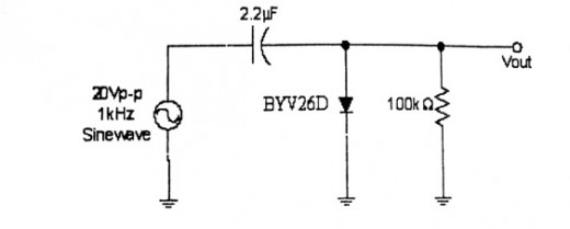
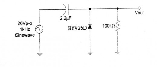
A Diode Clamper is one of the many applications of diodes. It is a configuration of a circuit wherein the diode “clamps” or shifts the waveform of the input voltage along the y-axis, i.e. its direct current value is changed but the peak to peak value, and the shape of the waveform stays the same.
Clamper circuits are used to restrict a signal from exceeding a certain value. In a clamper circuit, a diode and a capacitor is used in combination to attain this purpose. A DC source may also be used to “bias” the waveform, hence, further modifying the signal. The capacitor is connected in series with the signal source and the diode is connected parallel to the load. A bias, if added, is connected in series with the diode. The bias can be connected either polarity connecting the anode or cathode of the diode, depending on what result is wanted or to what direction the signal is biased. The diode can also be connected in either direction depending on which direction the signal is to be clamped.
There are four types of Clamper circuits: Positive Unbiased, Negative Unbiased, Positive Biased, and Negative Biased. Unbiased clamper circuits are those that only use diodes and capacitors while biased circuits are those that use DC sources. Positive and negative refers to which direction the waveform is shifted. If it is shifted upwards, then it is either positive biased or positive unbiased. The diodes in these circuits are connected such that the cathode is connected to the positive end of the signal source in the positive cycle. If it is shifted downward, then it is either negative biased or negative unbiased. In these circuits the diode is connected so that the anode is connected to the positive end of the source during the positive cycle.
For clamper designs, analysis is always started on the first forward bias and the capacitor polarity should be such that the positive terminal of the diode is connected to the cathode of the diode and the negative terminal of the capacitor is connected to the anode of the diode.
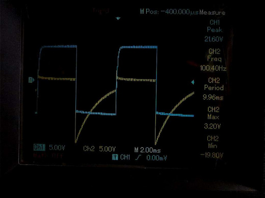
The capacitor charges and discharges during a single waveform cycle so the time constant, τ = RC is important. The time constant should be large enough so that the capacitor does not discharge significantly during the diode’s reverse bias state. Else, the resultant waveform will be tapered.

