Some Details on My Projects


Introduction
As part of writing my memoir, I decided to include some details on projects that may have some historical value or interest. Not to focus on the technical aspects but the general concept and perhaps lessons learned.
- March 2016
Loop Adapter (1974-1975)
The Loop Adapter project was a part of Future Systems IBM was developing. Even though this FS was not adopted, it has some very ingenious concepts that you may find interesting. This was a time before the internet and WiFi. IBM's design principle was always dictated by the three letters RAS. (Reliability, Availability and Serviceability). Any machine IBM build must be reliable, and available for the user and easy to service in the event of any breakdown. These principles were around when the Mainframe computer was IBM's primary business. These machines were very expensive and located in a clean room with raised floors and were running 24 hours a day to get the maximum usage.
The idea of the loop adapter is to connect a network of computer hardware system with a dual loop configuration. This system will have the capability to automatically reconfigure in case of a communication breakdown such as a cable being cut. The system would be smart enough to detect the break, re-configure the network by "wrap around" and complete the connection all without user intervention.
The CRC checker is part of this unique design. The problem with sending a string of one's and zero's such as 110111000011110010101... from point A to point B is that the communication line may experience some noise or static. In order for the transmission to be exact, a simple scheme is to generate a code of 16 bits to be appended to the end of the data string at point A. On the receiving point B, a checker is monitoring the string and if all the bits are correct, the result would be all 16 bits of zero. Any non-zero bits will mean that one or more of the bits were in error and a re-transmit signal would be issued. The math behind the CRC is exact. There is an equation that describe how this works. The beauty of this design is that the logic for the generator is exactly the same as the checker. This was an elegant solution to a real problem. It is still in use in many communication systems today.
ALU (Arithmetic Logic Unit) (1975-1978)
When most people speak about the computer, they think of it as this complex technological marvel that can replace the human brain someday which I doubt but that's the subject for another hub. They have no clue as to what the computer is. In reality, it is as simple as the diagram you see here. Yes, a computer can do all kinds of things including word processing, spreadsheets and graphics manipulation etc. That's the creation of application programs designed by smart programmers. The computer hardware itself is simple.
The best analogy I can come up with is the human language. In English, we have 26 alphabets and 10 digits and a handful of punctuation marks. Yet, with that, we can create all kinds of documents including some great poetry, speeches, our Constitution and great works of fiction. It is the genius of the writers and poets that makes it come alive.
The computer is the equivalent of the alphabet. A few simple instruction set, allow the microcode programmers to create the long set of complex operations that we are used to. The simplest operation in a computer is addition. Adding two numbers is the basic operation that can be used to perform all kinds of advanced mathematically functions. Just as an example, you can perform multiplication by adding the same number a multiple of times.
Logic Design For Integrated Circuits (1975)
One of the first thing I learned in IBM was logic design. This is the part that control all digital circuits and electronics. In the arena of integrated circuits, the idea is to pack as much logic circuits onto a silicon chip as possible. This allows for faster processing and lower power usage. It also is very difficult to manufacture and test. It takes a long process to create an integrated circuit onto a wafer of silicon and then diced to produce the individual chips. The chips are then individually tested to verify the circuits are flawless. The number of chips that are good is the yield. Typical yield factor runs about 10-20 percent range Depending on the density of the chip.
The part I would like to focus on is the testing of these chips. How do you make sure a chip of thousands of logic gates are manufactured correctly when you can't probe the internals. IBM engineers came up with the brilliant solution called LSSD which stands for level sensitive scan design. This proposal require the logic designer to follow a set of strict rules which then allows the testing phase to proceed automatically with a set of computer generated test patterns that completely verify the internal design. It was ambitious at the time, the early 1970s, but they were necessary to produce the many machines that IBM were designing and delivering to their customers.
What were the rules?
- only D latches were allowed.
- they must be clocked by a set of system clocks.
- every latch has a second gate B, part A feeds part B.
- these gates are daisy chained together in a serial fashion.
- an input pin feed the first latch part A and an output pin from the last latch part B.
- two extra clocks are added for testing use only. The first clock set the data into latch A and the second clock sets the data into latch B.
All logic designs consist of two portions, a combinatorial logic piece and a set of latches. They also consist of some input signals and output signals. By adhering to the above design rules, the final logic design lends itself to being tested 100%. That means every latch would be able to be turned on and off and every logic gates will be able to be exercised with all possible combinations. When a design is completed, an automated program can be run to generate the optimum test patterns to be applied to all the input pins and all the output pins can be measured for the proper states. At testing phase, the program can determine whether a given chip will pass or fail. That is pretty amazing when you think about it. It does comes with a price. The overhead in both circuits and I/O pins comes to approximately 20% of the real estate. It is a price worth paying when you want to make absolutely sure that the chip manufactured will perform flawlessly in the field. That was one of IBM's selling point. RAS, reliability, availability and serviceability was the design motto.
Binary To Grayscale Conversion (Patent)
One of my patent while working on digital imaging is a method for converting a binary image to a grayscale image for display. The concept is really simple. When you have a high resolution digital binary image say 300 dpi, it is captured at much higher resolution for display purposes. A standard FAX document is usually captured at this resolution. A typical PC display at the time can only show 1024x768 pixels. In order to show the document on the screen, the data is scaled down to fit the resolution of the display. If the original image in 2400 bits wide, you need to reduce it by at least a factor of 2. The easy way to do this is to throw away every other bit. My novel idea is to convert the 2x2 bits into a grayscale pixel. In this case, it can be (0, 64, 128, 192, 255) depending how many of the 2x2 is a 1 or 0 value. The advantage of doing it this way is that you will end up with a better quality image. The quality will improve, the higher the capture resolution. At 600 dpi, you can reduce the 4x4 bits into 16 levels of gray. The monitor can show up to 256 levels of gray.
CY512 Motor Controller
A technical detour which may give you some insight on technology and its pitfalls. The Pro/3000 scanner is the best of breed at the time. Embedded in this high resolution scanner is a standard motor controller chip named CY512. This controller allows the scanner head to stay in synch with the programmable integration speed as it glides across the document capturing the Red, Green, and Blue separations. It also allows the scanner head to return to the home position ready for the next scan. In most other designs that uses this chip, it is a fixed program that repeats the exact programmable steps once it is tested and determined to work properly. In our case, we have made it a more robust system by changing the variables with each new scan. That is because we want the flexibility to capture a cropped area of the image. Thus, every new scan would require a new set of parameters to control the motor most efficiently.
On one occasion, while running a test scan, the operation failed. It was an intermittent error one that are the hardest to find. After some debugging and checking with our hardware designer, we actually found a design bug of the CY512 chip - an off the shelf part. Apparently, in some unique circumstance, when the exact number of micro steps instructed crosses a certain boundary, the CY512 goes haywire. It was not suppose to happen - yet Murphy's Law strikes again. The fix was a simple programmable instruction to handle this exception. However, this was an obscure bug that took a long time to show up. It is one of those rare cases when standard testing procedures would not catch. The only sure way we could have found this bug was to try all possible scans which was unrealistic. It goes to show that even if something is working well for years, it does not guarantee it will work always.
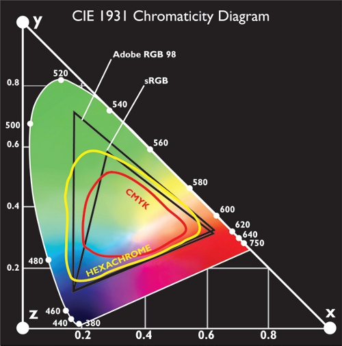
Color Science Detail
The Wyeth project was successful because we made the effort to learn about color science. It turned out that having a true color reproduction of a painting is very difficult. That's because the appearance of color is dependent on the view conditions and the color temperature of the lighting. It also varies from display to display and for printing on paper. The science depended on having the proper color filters of red, green and blue in the camera design; the proper lighting for both reflective and transmissive scanning; a calibrated monitor using special equipment and a standard viewing booth of 5000 degree Kelvin color temperature (daylight). In addition, the color palette of a display is limited by the CRT. Even though we capture a 24 bits per pixel (giving us 16 million color palette), the display or print can only show a subset of those colors.
Assuming we do everything right, there is no guarantee that a given capture will end up correctly once transmitted from one computer monitor to another. However, there was one saving grace. Our human visual system has a built in color adjustment. It is called "memory" colors. Our eye will see any image that contain flesh tone or grass or sky and adjust the over all colors to "look right" within reasonable limits. As long as the image is approximately close, the eye will do the rest and most viewers will not know the difference. The other important aspect of color is getting the "white point" correct. Our calibration process was to measure the white background and use it to adjust our color capture. We used the MacBeth color chart for our calibration.
Data Compression (1993)
Some of my past projects were dealing with digital media such as images and videos. The amount of data compared with textual data is overwhelming. The size of the data affects both storage and access time and also transmission. To reduce the size of data, data compression algorithms and standards have been established to keep the data more manageable. The CCITT is an international standards organization that oversee such activities. Their activities affects both hardware design and software implementation of many communication related equipment and programs. A good example is FAX documents. The Group III standards of bi-level images adopted a Huffman coding scheme based on statistics. A set of typewritten documents agreed upon by all members were chosen to be the standards. Various algorithms were developed to compete for the most efficient and highest compression ratio. The winner were chosen to become the standard algorithm that all manufacturers would implement. This is the reason that a FAX scanned with one brand of machine can be sent via telecommunication lines and received by another brand of equipment and decoded and printed any where around the world.
In specific, dealing with coded data of images, there are several data types. There are binary data, grayscale data and color data. Compression comes in two flavors, exact compression and lossy compression. In exact compression, the data is coded in such a way that it is 100% recoverable. The compression ratio is usually much lower and image dependent. A 3 to 1 compression is perhaps the best can be done with exact compression. In lossy compression, a much higher compression ratio is possible. The theory being that a small error in data compression would not change the overall content of the original image. It is a trade-off between size and quality. This is important when transmitting these images over networks such as the web or slower telephone lines. For example, in JPEG compression scheme, the user can choose a quality factor which in turn will determine the data size. A high quality option may give a 10 to 1 compression ratio while a low quality factor can lead to 100 to 1 compression. JPEG is also a compression standards group stands for Joint Photographic Experts Group.
For example, if you have a digital camera that is 12 Megapixel resolution. It has the capability to create a raw uncompressed file of 36 MB. (3Kx4Kx3) A compression of 10 to 1 will bring it down to 3.6 MB but a 100 to 1 compression will bring it down to 360 KB in size. The important thing is, the actual image may not look that different. Depending on the content, only a trained eye can spot the "errors" contributed by the compression.
I was fortunate enough to work in a small group where some of my colleagues were actually involved with the standards committee and also contributed to the development of the algorithms. They also wrote the de-facto textbook on data compression. Next time you send a photo on your smart phone, you have these people to thank for getting the data to your friends almost seamless and instantaneously. That is the magic of compression.
Summary
This section of my memoir is to provide insight into some of the projects in more detail. Having received feedback from others, I decided to move the contents of this section from the body to a separate chapter. I realize some of it is technical in nature but never the less, I felt they may provide some useful information.
Navigation (My Life Story)
Some Related Info
© 2016 Jack Lee


