What Should I Expect to Receive from my Architect/Designer?

So you want to hire an architect/designer for your construction project. Besides professional services, what exactly should you get from him/her throughout the project? Pretty pictures on a piece of napkin? or an elaborate model?
Tangible "stuff" that an architect/designer will give to the client is called "deliverables". In general, they can be divided into 4 categories - drawings, specifications, models/renderings, and Material Samples. You should receive them at a pre-agreed interval based on your project schedule and progress.
Plan Cut LIne

Drawings
Drawings are typically shown on 24"x36" paper size for residential projects. It can be drawn on a larger paper size such as 30"x42" or smaller size such as 11"x17". It all depends on the size and complexity of your project. The key is to make sure that your drawings are scalable, meaning you should be able to measure the drawings with a scale or ruler to find a dimension.
-
Site plan – also known as plot plan. This drawing shows the relationship/dimensions of the house/structure to the property lines. For smaller projects, minor landscaping and site utility information can also be shown on the this sheet. For larger projects, the landscaping and site utility information is often shown on separate drawings.
-
Building Plan – It's an enlargement of your project area. Verify that the following information is provided:
The darker lines are cut lines, typically 4' above the finish floor. Lighter lines are usually things below the cut lines. Dashed lines refer to things above the cut line. See example above.
Is the plan drawn to face of stud (framing) or face of finish? This should be clearly dimensioned. Dimensions to face of framing is generally acceptable unless you are expecting a specific clearance for a specific piece of furniture or artwork. In this case, make sure that the dimensions shown on the drawing are to face of finish.
Preliminary furniture layout should be shown during Design Phases but not on Construction Documents. This is important for electrical/CATV outlet location coordination.
Flooring change locations. This can be a simple line on the drawing showing the transition location between carpet/tile/wood, etc.
-
Exterior Elevations - if the project involves enlarging the building footprint, you'll need exterior elevations. Vertical dimensions should be shown in relation to a datum point such as the exterior grade, interior finish floor, or framing. Exterior finish material and color scheme should be noted on the drawings. Verify trim sizes, and locations. Check for building height, window and door height and/or alignment with existing windows and doors. You don't have to select the colors yet, but have a general idea of how many different colors you want, and where the transition will be.
Section Cut

-
Sections - Building sections are vertical cuts through the building. It is specially critical for projects on a sloped site. This shows relationship between rooms, site, and different levels. It is not important to repeat information already shown on interior elevations as long as each room is clearly labeled and crossed referenced.
Thick lines are cut lines. Lighter lines are things beyond. Dashed lines are things hidden by objects or things in front of the cut lines.
You may or may not have wall section for your project. Wall section shows detail construction of a wall, including every single piece of wood, etc. It is only necessary if you are not using conventional framing system, or if the wall is supporting unusual stuff.
-
Interior Elevations - Show vertical dimensions as they are related to floor and ceiling height. Locate and dimensions cabinet heights and layout, special wall finishes, mirrors, art work. If it is critical to you, ask that wall switches and outlets be shown on the interior elevations as well.
-
Reflected Ceiling Plans (RCP) - Imagine a mirror on the floor looking up the ceiling, that is reflected ceiling plan, also known as RCP. For small projects with fairly straight forward ceilings, an RCP may not be necessary. You might be able to show everything dashed on the building plan. If the project has complicated ceiling with different finishes, heights, etc, an RCP would be a must. RCPs are opposites of building plans. All items on the ceiling will be shown solid. All items on the floor will be shown dashed. Cutlines are still heavier than non-cut lines.
-
Details - Details are enlarged drawings of a specific area that show relationship between materials. Details can be drawn in plan view, section view, or 3D axonometric view.
If the project is small enough, you may have mechanical, electrical, and plumbing information shown on architectural plans. Structural drawings will most likely still be separate.
Models/Renderings
You may request your architect/designer to provide you with a model or color renderings. A model can be a physical model or a computer generated model. More and more people are moving towards the computer generated model because it takes up less room, is more portable, and often you can place the model on your site and generate lighting/shadowing effect.
Color renderings of your project can be done be hand or by computer as well. Discuss the view and media with your architect/designer.
Specifications
Specifications states the quality of the materials for your project. It normally follows the Construction Specifications Institute (CSI) format. Here are the standard formats for specifications.
-
Sheet Spec – This works best for small projects. The product description/specification is shown directly on the drawing sheet; hence, sheet spec.
-
Outline Spec – This is a written document separated from the drawings. It identifies major materials and systems in an outline format and establish the general quality level and/or manufacturer. It tells you the final product selection without telling you how to install it.
-
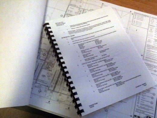
3-Part Spec – Also called the “Project Manual”. This is also a written document separate from the drawings, typically large enough to be bound as a booklet. The booklet is organized under CSI format. Each section is further divided by 3 parts, hence the name. Part-I lists general information about the section such as system description, reference, quality control, submittal requirements, etc. Part-II describes the product such as manufacturer, color, finishes, etc. Part-III outlines execution requirements such as preparation, cleaning, warranty, etc.
Material Samples
You can request the designer/architect to put all the materials and colors on a board for your reference. If your project needs to go through public hearing, most likely the Planning Department will require a material board for exterior materials only. The Planning Department normally doesn't care about interior finishes or layouts. Producing a material board is a laborious task, and the final product is often bulky and difficult to store. It might make sense to ask for a separate binder that stores material samples in them. This is easier if you decided to change a sample, you won't need a brand new board. The key is to make sure you have the manufacturer, color, and style information in case you need to order extras in the future.
Summary
You will not receive all of the deliverables at once. Drawings are normally submitted several times to show the progress of the project. Verify the deliverables with your local government who will be reviewing and approving your project. Make sure that the list of deliverables, at a minimum, meets the their requirements. Also include the schedule of deliverables in your agreement with your architect/designer to confirm expectations.