DCC (Digital Command Control) Model Railroad Lighting Idea


Background
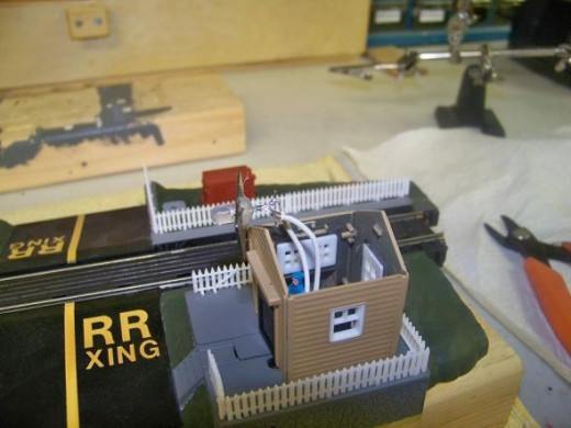
Abbreviations I use in this Lens:AC: Alternating CurrentDC: Direct CurrentDCC: Digital Command ControlLED: Light Emitting DiodeI purchased the Walthers Life-Like Trains Operating Switchman (Item 433-8310) from Amazon for my HO Scale, DCC controlled, model railroad layout. The switchman comes out of his house when a train passes. It is operated by the weight of the train on the track connected to the base of the switchman's house. The switchman's house also has a small incandescent bulb installed for lighting effect. This bulb is typically connected to the AC terminals of your DC power pack.
Caution!!!
Proceed at your own risk!! If you decide to build the circuit described in this Lens, I am not responsible if you:-Cause damage to your DCC Command Station, Booster, or Throttle.-Cause damage to the decoders in your locomotives.-Damage any electronics attached to your model railroad layout.-Burn your house down.-Cause the moon to leave Earth's orbit (like in Space 1999)-Create a hole in the Ozone layer.-Form a black hole next to your model railroad layout.If you assemble this project correctly none of the above calamities should happen.
DCC Voltage
Knowing that with a DCC system, there is a constant 14volts AC on the track at all times, I decided to use the track to power the incandescent bulb in the switchman's house. I connected the wires of the bulb directly to the Power_Loc track built into the base of the Operating Switchman assembly.
The Problem
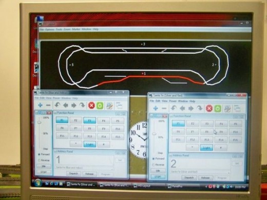
The incandescent bulb in the switchman's house has a nice glow when it is driven off of the power on the track but I ran into another problem. The incandescent bulb causes enough current load on the track that it triggers my Digitrax BD4 Quad Occupancy Detector to think a locomotive is on that section of the track. The Digitrax BD4 Quad Occupancy Detector is a current load sensing device which typically is used to sense the current draw of the motor in a locomotive in a specific block of track. I am using JMRI software to monitor my HO layout on a computer. The Digitrax PR3 computer interface allows my computer running JMRI software to interface with my Digitrax Zephyr Command Station/Booster/Throttle and BD4 Quad Occupancy Detector so that blocks of track that is occupied with a locomotive shows up as red in the layout. As you can see from the picture Block 1 is showing up in red indicating that a train is present even though one is not.
The Solution
Generally speaking, LEDs require less current than an incandescent bulb. I figure that I could just replace the incandescent bulb with a LED with necessary currently limiting resistor. This would drop the current load below the threshold value causing the Digitrax BD4 Quad Occupancy Detector to alert of a train presence.
The Enhancement
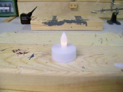
Instead of just using an ordinary yellow LED, I thought it would be cool to simulate the effect of a candle or oil lamp flame in the switchman’s house. My daughter was playing with a battery operated flameless candle when I got an idea. Why not strip the electronics out of one of these flameless candles and have it light the switchman’s house?
Disassembling the battery operated flameless candle
To my surprise there is nothing to a flameless candle but a 3 volt lithium battery, a switch, and a special LED that has built in electronics that causes it to flicker.
Creating the proper circuit
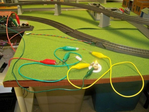
The first step was to come up with a circuit used to power the flickering LED from the DCC track voltage. As the component count was low, I used alligator clips to connect the components needed to each other and to the track. I used the flameless candle housing with the battery removed as the base for the flickering LED during these experiments.
The Circuit
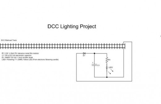
After some experimenting I came up with the above circuit to power the flickering LED from the DCC track voltage. Diode D1 convert s the DCC AC current to DC current. C1 acts as a filter capacitor and removes the ripple from the incoming DC. R1 drops the incoming voltage down to around 3 volts, the voltage level needed for the flickering LED. The flickering LED has a built-in current limiting resistor and if the rectified voltage from the track were about 3 volts instead of 14 volts we would not need R1.
Model Train Sets on Amazon

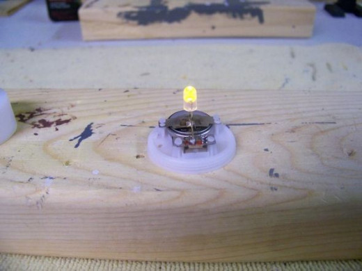
Removing the flickering LED from the flameless candle
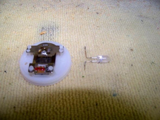
The first step is to remove the flickering LED from the flameless candle base. First make a note of which lead of the flickering LED is connected to the positive side of the battery and mark a small plus sign next to the lead indicating polarity. Unlike incandescent bulbs, LEDs are polarity sensitive and will only light when the polarity is in the right direction. De-solder both leads of the flickering LED form the flameless candle base.
Removing the incandescent bulb from the switchman’s house
The next step is to remove the incandescent bulb from the switchman’s house, de-solder the wires from the base and shank of the bulb. Remove the bulb from the rectangular holder.
Installing the flickering LED
The next step is to install the flickering LED in the rectangular and holder then solder a wire to each lead, trim the leads and apply a small dab of hot glue to hold the flickering LED in place.
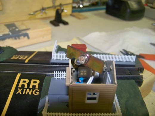
Install the flickering LED assembly in the switchman’s house
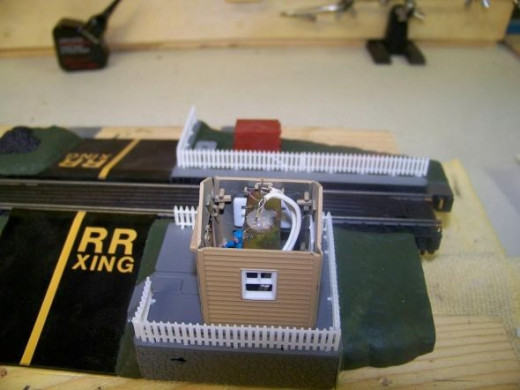
Install the flickering LED assembly in the switchman’s house by placing the rectangular holder in the notches built on the inside of the switchman’s house.
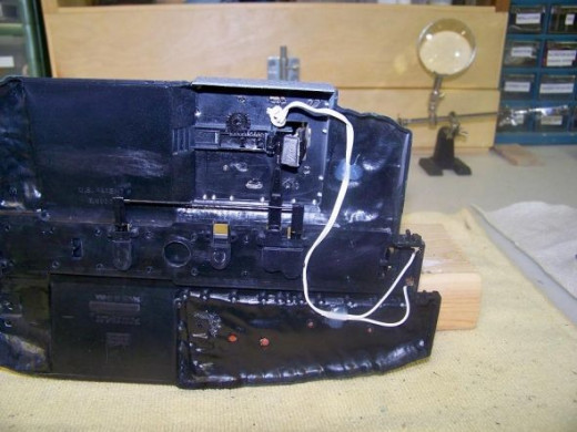
Install the electronics in the base of the Operating Switchman
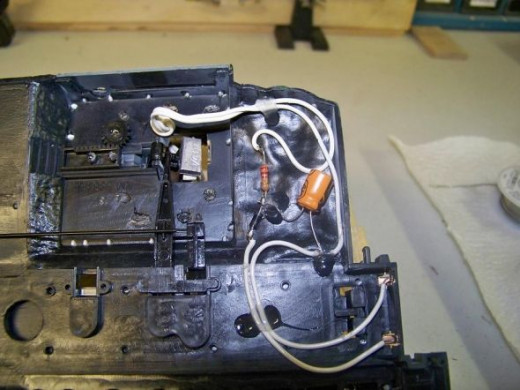
The next step is to install the electronics in the base of the Operating Switchman. Wire it per my schematic presented earlier and the physical layout presented in the above picture. Use a dab of hot glue in various places to keep all the electronics in place.Please Note: The positive lead of the electrolytic capacitor C1 must be attached between D1 and R1. Do not reverse the leads of the capacitor.Please Note: The positive lead of the flickering LED must be attached to resistor R1. Trace the wire back to the flickering LED and identify the wire that connects to the lead that has a plus sign next to it that you marked earlier. If the wires are reversed the flickering LED will not light.


Testing

Attach the train rails of the Operating Switchman to your layout. Replace the roof of the switchman’s house. Apply power from your DCC booster to the tracks of your layout. You should notice a warm flickering glow from the inside of the switchman’s house. This effect is even cooler when the lights are turn off.
Troubleshooting
Not seeing the warm flickering glow coming from the switchman's house? Check the following:-Verify that your DCC booster is applying power to the track. You can use a multimeter set to an AC range to test this. If you touch each rail with one of the leads of the multimeter it should read around 14 volts AC. If no voltage is present try removing the Operating Switchman rails from the layout then check voltage on your layout's rails again. It could be that you have introduced a short by incorrectly wiring the base of the Operating Switchman.-Verify the electronics wired in the base of the Operating Switchman based on my schematic.-Try reversing the wires to the flickering LED, you could have the polarity switched.
Conclusion
With a little ingenuity you too can take common household items, like the flickering candle, and create neat effects for you model railroad layout like the flickering light in the switchman’s house described in this Lens.


