Build Your Own Simple, Sturdy WorkBench
1. Disclaimers
This wooden work bench has been designed on a 3D CAD system (Autodesk Inventor) using millimetre (mm) sizes. It is acknowledged that metric is not an ergonomic measurement system, may be less familiar to some, and is not ideal where the material is in inch standards as here.
The softwood used is a nominal inch sized (1½" x 2½"), as is the MDF sheet area (8' x 4'). Any conversions shown in the text are approximate. Dimensions shown without units are mm. The plans are available in pdf format and are free for non-commercial use. The bench is built entirely at your own risk.
2. Description
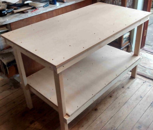
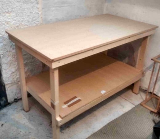
This is a sturdy wooden workbench built from readily available materials. The worktop and shelf are 18mm (¾") MDF - a semi hard composite sheet which is damp resistant and far superior to the ghastly chipboard.
The frame is P4S (planed four sides) softwood 38 x 63 (1½" x 2½") with rounded corners. Joints in the frame rely for their strength on a single wood screw and PVA wood glue. There are no complicated joints such as mitres or half joints.
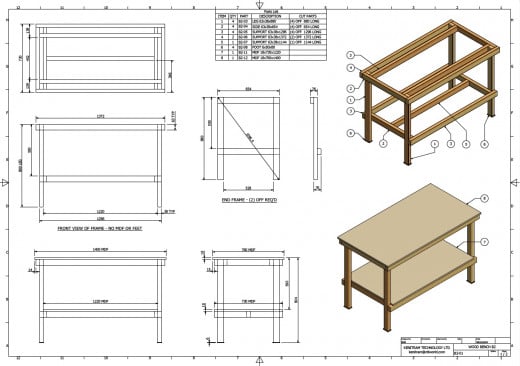
Download Bench CAD drawing plans (pdf)
3. Materials and Equipment.
All the wood materials and a cutting list are shown on the plans.
The 18mm x 8' x 4' MDF sheet should be cut by your supplier on a panel saw for accuracy and convenience of transportation. Suppliers include B&Q, Homebase and Wickes. Check before buying that the sheet has no dents, bruises or delaminations.
Select 38 x 63 (1½" x 2½") softwood frame lengths that are straight (sight along them in the store) without shakes (splits), resin pockets or overlarge knots.The softwood will have to be cut to length, probably not by the store. Ideally this should be done on a crosscut or cutoff saw; if not then a hand saw with a mitre block.
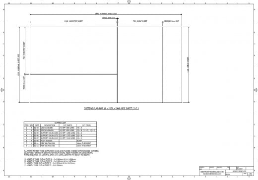
The length of frame parts with the same nominal length must match within ±0.5mm, but the actual length could be ±1mm. So all the Side members could be 655 long, rather than the nominal 654mm. It may be advisable not to cut the centre Support (nominal 1144mm) at this stage.
Use PVA wood glue, exterior grade for all wood joints. The glue is critical - get the right stuff. Do not use contact adhesive, No-Nails, Gorilla Glue, epoxy or any other.
Two sizes of plated steel woodscrews were used, both with Pozidriv countersunk heads: for the framework use (22) off Ø5mm x 65mm; and for fastening the MDF to the frames use (56) off Ø3.5mm x 40mm. It is essential that the part being fastened has a clearance hole for the screw, either Ø5.0mm or Ø3.5mm respectively.
Failure to use the correct clearance hole size will prevent the joint closing up properly resulting in a weak joint.
General tools required are G clamps; a battery power drill; drill bits of Ø2.0, Ø3.0 as pilots and Ø3.5, Ø5.0 as clearance; a countersink bit; Pozi screwdrivers; a square; a tape measure and a pencil.
4. Construction
Study the plans and the photographs. The plans are available to download as high resolution PDF documents from the link on this page as well the two photos shown. Please note, there are two pages to the PDF plans.
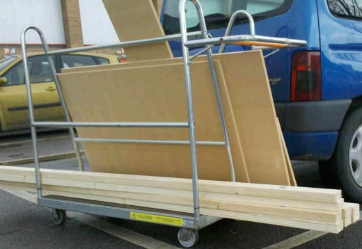
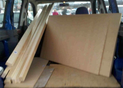
Photo P01 shows the 2.4m frame softwood and the store cut MDF on a trolley as bought.
P02 shows the wood in the back of a Berlingo car. The completed built bench also fits in, just.
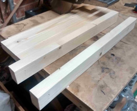
P03 shows the frame parts cut to length on a radial arm saw from the softwood P4S 38 x 63 (1½" x 2½") x 2.4m lengths. If you have no type of power cut-off saw, cannot get a friend to cut the lengths, or a joiner, you will have to cut them with a hand saw in a mitre block yourself. It may be advisable not to cut the Support 1144mm at this stage, see later in the Construction description.
Step 4A
Once the correct lengths are cut, the first construction is (2) off End Frames, as drawn on the plans.
Each End Frame is identical and constructed separately.
Initially all joints are just screwed together without gluing.
Step 4B
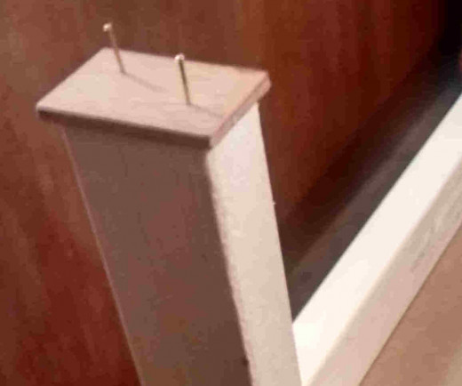
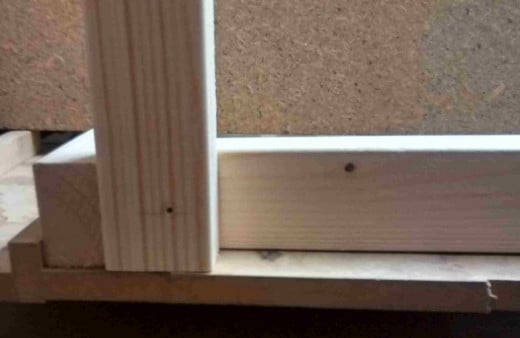
Take (2) off Side parts (654 long), mark out for one drilled hole, in the position indicated in P04, in each end. The position is not critical but should be offset from the centre in both X and Y directions by about 7mm (¼"), so that later screws, similarly offset, will clear by about 13mm (½").
Drill a Ø3.0mm pilot hole through each end of the two Side parts, ideally on a bench drill, but if not then carefully, ensuring squareness, using your battery drill.
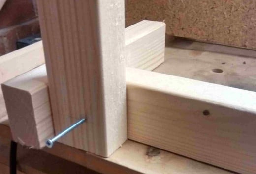
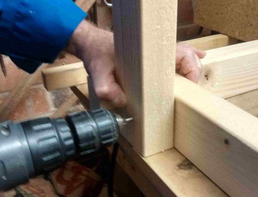
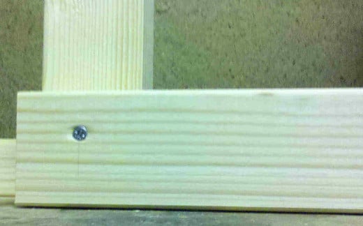
Refer to P04 and P05: assemble a pre-drilled Side with a Leg ensuring that the faces are true by using block off cuts to line up, as shown. Then drill through the pre-drilled Side into the Leg using the Ø3.0 drill bit to a depth in the Leg of about 16mm - 20mm, as shown in P05.
Step 4C
Open up the Ø3.0mm hole in the Side to Ø5.0 and partial countersink to about Ø7 to Ø8mm (no photo). Do not touch the Ø3.0mm pilot hole in the Leg
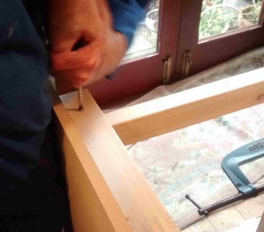
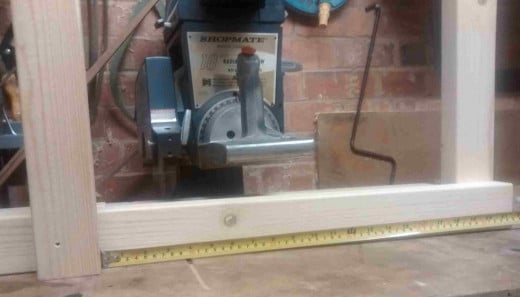
Insert a Pozidriv screw Ø5mm x 65mm into the Side as shown in photo P05. Drive home using the correct size screwdriver as shown in P06 and P07 to achieve a firm joint but do not fully tighten at this stage.
Repeat the above process for joining a second Side part to the Leg, as shown in P08. Measure carefully the distance between the (first) top Side and the second Side used to support the Shelf. Make sure that the two Side parts are on opposite sides of the Leg, see P08.
Repeat the above process for screwing a second Leg to the two Sides.
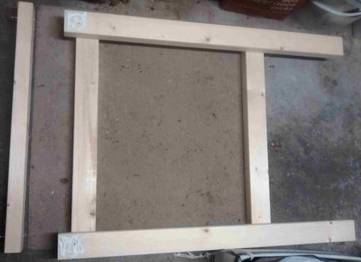
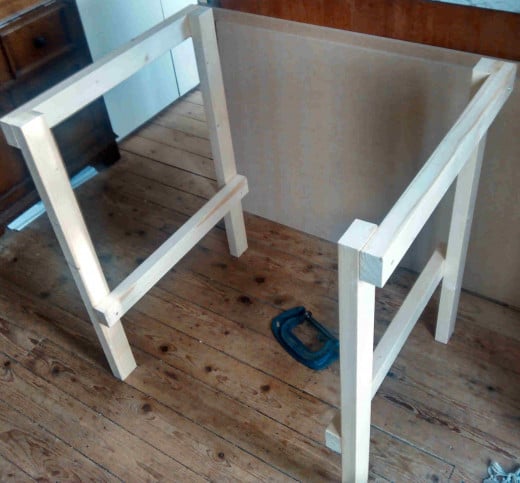
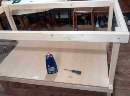
Photo P09 shows the start of the PVA gluing process. The top Side part is shown ready to be placed onto the Legs after application of the PVA glue and then completed with one Ø5mm x 65mm wood screw at each end.
Turn over the End Frame and repeat the process for the Shelf level Side part.
Step 4D
Immediately the joints are made on one Frame with the glue and the screws, whilst the PVA glue is still wet, square up the End Frame initially using a try square. Then measure both diagonals across the Frame as indicated on the plans and adjust the Frame until the diagonals are equal. Check again with the square and when satisfactory leave the Frame to dry overnight.
Repeat the same process to make the second Frame. Photo P10 shows both Frames complete standing on the floor used in the next stage of the Bench construction.


Step 4E
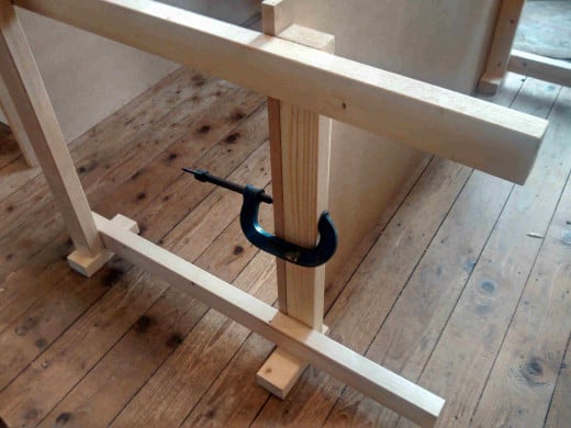
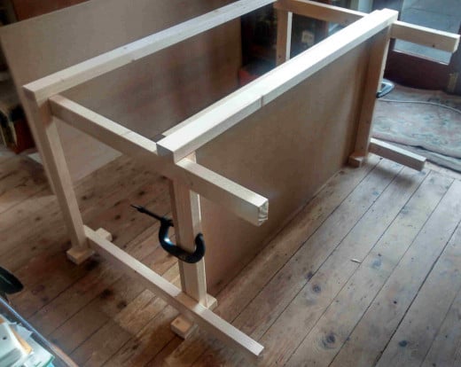
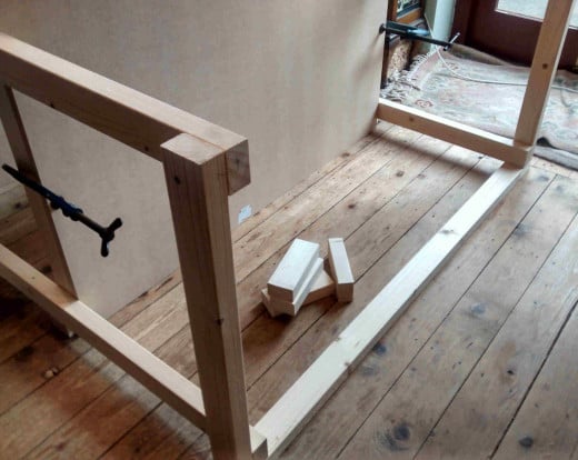
Put both Frames on their sides on blocks (offcuts 38 x 63) as shown in photo P11.
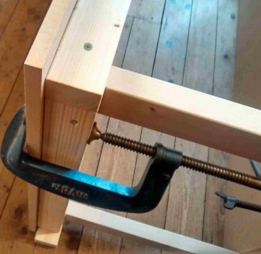
Clamp the pre-cut Shelf MDF sheet to the shelf support Side parts using G clamps as shown in P11, P12 and P13.
The MDF should sit directly on the floor and be tight and square to the Legs.
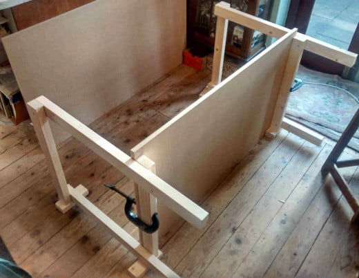
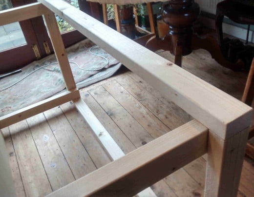
Place a Support 1372mm long at the top of the Frames, as shown in photo P14
Offer up and clamp the pre-cut Worktop MDF sheet.
Make sure that the Support ends are flush to the Frame Side parts, and flush to the MDF, see P15.
Step 4F
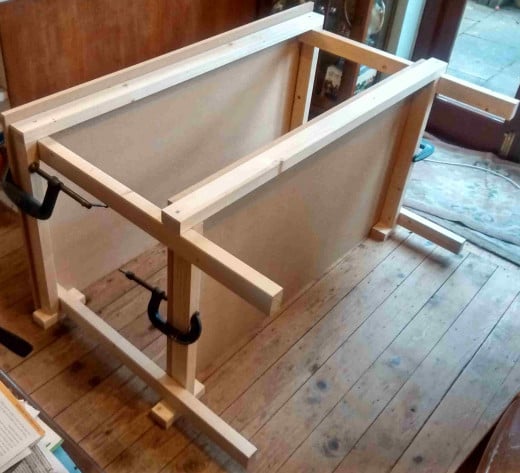
Place a Support 1296mm long against the MDF Shelf, as shown in photos P14 and P15.
Mark out and pilot drill Ø3.0mm for screws to fasten the Supports to the Legs (not to the end grain of the Side members).
Drill out the Supports Ø5.0 and countersink, as before.
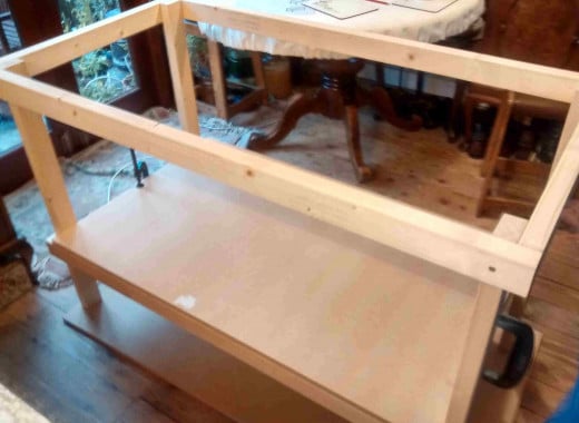
Dry join the Supports as shown in P16 and P17 with the Ø5mm x 65mm wood screws.


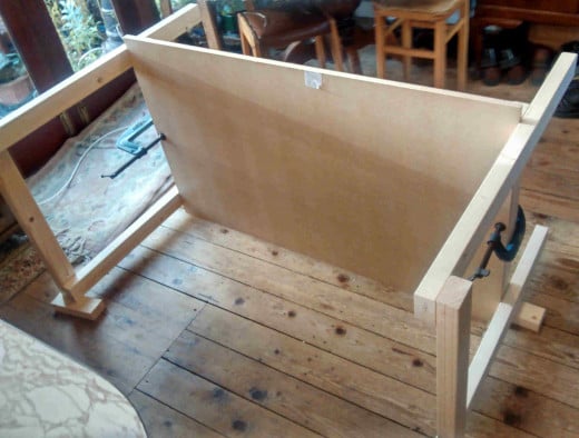
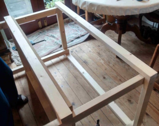
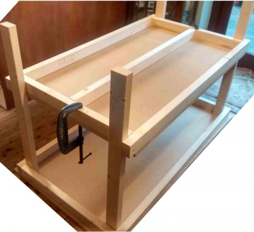
Unclamp and remove the Worktop, turn over the Bench and repeat the Support dry fixing process as shown in photos P18, P19 and P20. The Worktop can be re-utilised to line up the top Support, but blocks are not needed on the floor this time because the Supports are already fixed to the side sitting on the floor.
Photos P21 and P22 illustrate the almost complete, dry fixed Frame.
Step 4G
The final Frame job is to fix the centre Support, nominally 1144mm long, beneath the Shelf. Put the MDF sheet Worktop on the floor and turn the Bench Frame upside down on it. Measure the distance between the Frames under the Shelf: it should be 1144mm.
Cut the centre Support to the measured length and fix in place using two wood screws Ø5mm x 65mm into the end grain of the centre Support, as shown in P23.
Step 4H
The next job is to convert all the dry, screwed only, joints into fully PVA glued and screwed joints on the Frame. This is indicated in photo P24. As you progress ensure that all joints are screwed tight with some PVA glue squeezed out all round. Check that all joints are square and true before finally tightening the screws.
Step 4I
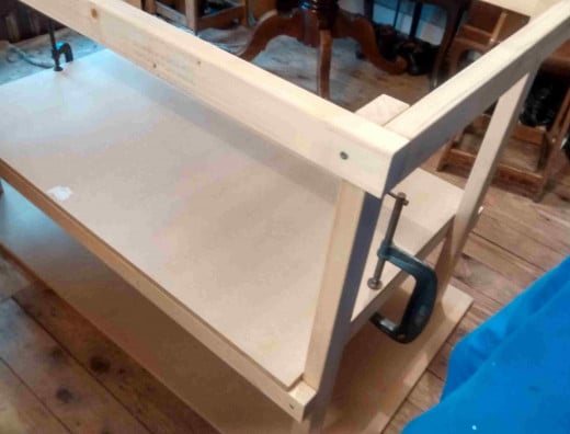
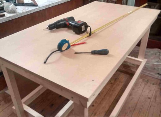
When the Frame glue is thoroughly dried it is time to fit the MDF Shelf and Worktop, as illustrated in P25. Mark out for the holes for the smaller wood screws Ø3.5mm x 40mm from the MDF to the centre of each of the Frame members, using a pitch of about 200mm and an equal offset at each end of the row of holes.
Use a pilot drill of Ø2.0mm to drill through the MDF and into the Frame member by about 12mm. Open up the holes in the MDF to Ø3.5mm to provide clearance for the small screws, and cut a full countersink to take the entire screw head. Smear PVA glue on the Frame members, line up the MDF on the Frame using screws in a couple of places, insert all the screws and tighten.


Step 4J
Fit feet made from 4mm to 6mm thick exterior plywood onto each Leg to protect the end grain, as shown by photo P26. The ply could be from the store scrap box or from scrap stock at home.
When the feet and all other joins are dried and set, turn the completed Bench over as in P27.
The final photo, P28, shows the bench in position in a utility room. It may be necessary to pack the feet to obtain a level Bench after checking with a spirit level.
