Wiring Electrical Switches
Types of Switches to be Wired
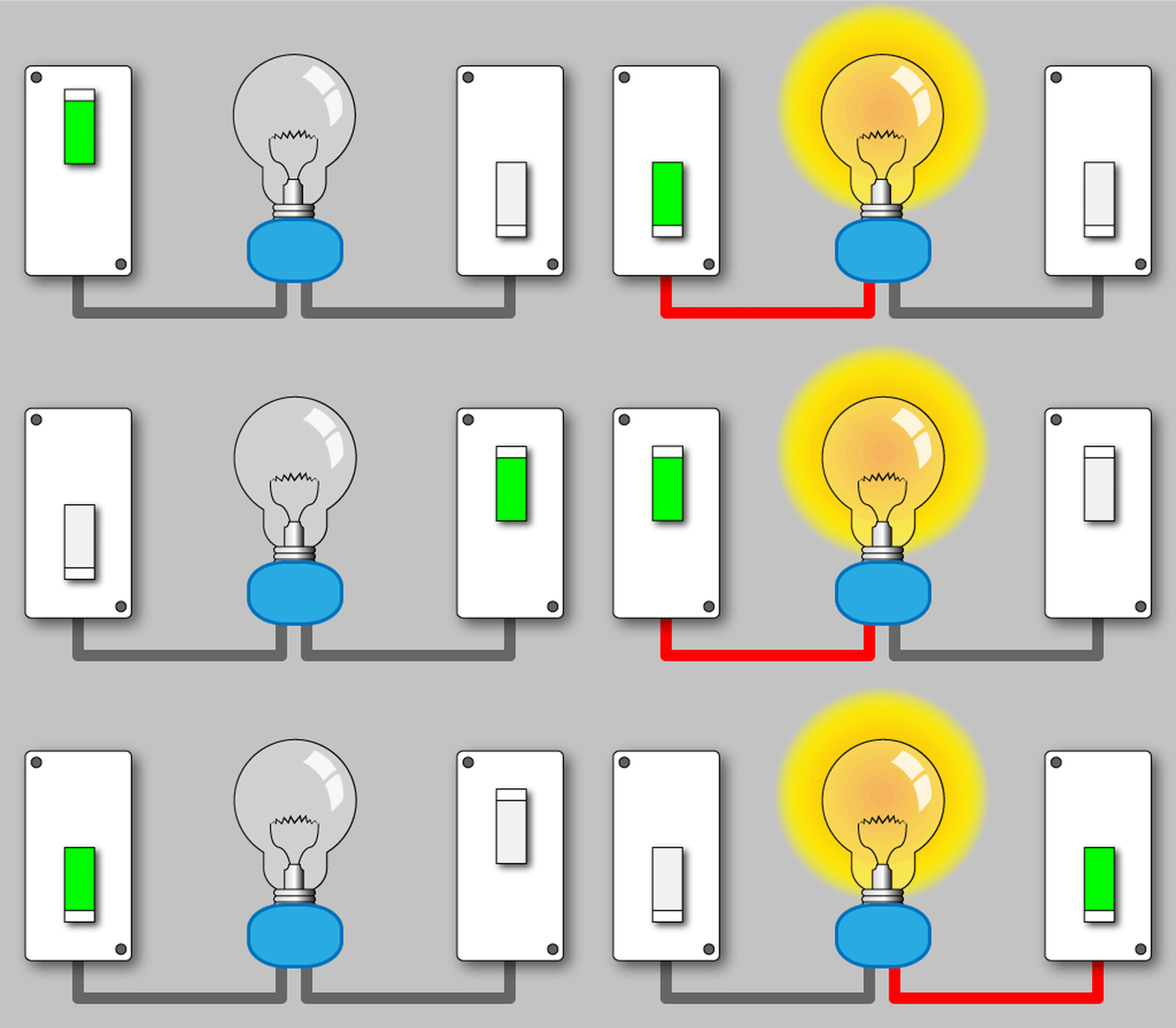
While there are literally thousands of different styles and types of electrical switches that can be wired for thousands of different purposes, this article is dedicated to the simple single pole, or two way, switch of the type used to turn lights on in your home.
If you are wiring a three way or four way switch, please view the articles about how to wire a three way switch and/or how to wire a four way switch. Other common switches such as some simple automotive switches will behave the same electrically as a house switch although the mechanics of mounting or attaching wires may be different, and this will be explained in the next section of this article.
As a professional electrician I have wired literally thousands of switches of varying types and styles over the years. It is not a difficult task at all, and something any homeowner can easily understand and do themselves with just a little work and understanding.
How Does An Electrical Switch Work?
At it's simplest, a switch is a mechanism to connect and disconnect two wires without physically removing the wires from the mechanism. It will thus require some way to attach the two wires to be connected to the switch, and all switches used in a home must also have a place the attach a ground wire as well. This wire, bare of insulation or colored green, has been required throughout the US for many years and is a very important safety feature.
The switch will have internal parts to make an electrical connection between the two wires and has the ability to either make that connection or, by flipping the switch, remove that connection. This is common to all two way switches whether they be for the home, in your car or the switch under the seat of your riding lawn mower that detects when you are sitting on the seat. A switch might turn on a light in your home, turn on the radio in the car or provide current to run the lawn mower if there is weight on the seat - it can do many, many different things.
In all these cases the device to be turned on (light bulb, radio, etc.) must have two wires to it. One wire is attached permanently (in the case of a car often using the metal body of the car as a "wire") and the other wire goes through the switch. When the switch is turned off it leaves electric current on only one wire and the device won't come on.
Wiring a Light Switch in the Home
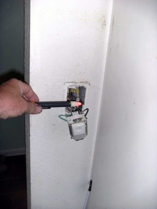
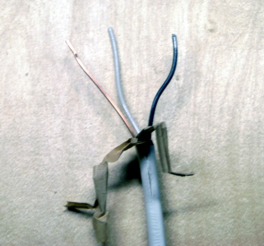
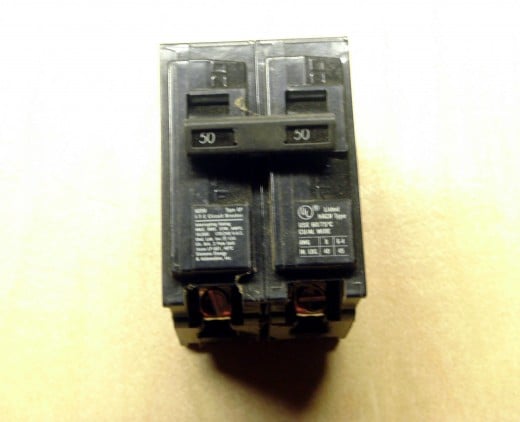
Most of the wiring in your home will be of the 120 volt variety; only the range, clothes dryer, hot water tank and a handful of other high energy appliances require 240 volts. The 120 volt circuit consists of a black ("hot") wire, a white ("neutral") wire and a bare or green "ground" wire. The neutral wire is always attached directly to the light or other device, the black wire goes through the switch, and the ground wire goes to both switch and light. The wire is usually contained in a cable, all three wires bundled together in an insulating sheath with the black and white wires having their own insulation as well as the sheath enclosing the entire cable. The cable originates in the panel, or fuse box, where it can be turned off by turning the correct breaker off or removing the proper fuse. Always turn the power off before doing any electrical work and preferably check that it is dead by using a non contact voltage detector or voltmeter.
There are two common methods of physically getting the wire to the light and switch in a home; which wires go to the switch is determined by which method is used. The cable from the panel box will go to either the light or the switch, and a second cable is always required between the switch and the light.
Power to the light first
In this case the cable from the panel box goes to the light box, where the light is, first. The white, neutral wire is then attached to the light at this point. A second cable, again containing a black, white and ground wire goes to the switch. In this case the white wire in the cable to the switch is attached to the black wire coming from the panel box with a wire nut and should be colored black with a magic marker or black tape to indicate that it is not a neutral wire. It is now a "hot" wire. The black wire from the switch is attached to the light. At the switch there will now be a black and a white (colored black) wire plus the ground. All three of these will attach to the switch. It should be noted here that the 2011 National Electric Code was changed to require that each switch box have a white neutral wire in it; this means that if the power goes to the light first the cable to the switch must have a white, black and red wire plus a ground. The white wire is attached to the white wires at the light but is then capped off with a wire nut in the switch box without connecting to the switch. With both black and red wires between the light and the switch there is no need to color any wires and the red wire is used rather than coloring the white wire and using it.
Power to the switch first
In this case the cable from the panel box goes to the switch first, with a second cable going from the switch to the light. There will be two cables (six wires) at the switch. The two white wires are spliced together with a wire nut and are not to be colored; both are still "neutral" wires. The two ground wires must be spliced together with a third short piece of green or bare wire that will go to the switch. The two black wires, one from each cable, go to the switch as well.
Using a Voltage Detector
Click thumbnail to view full-size

Attaching the Wires to the Switch
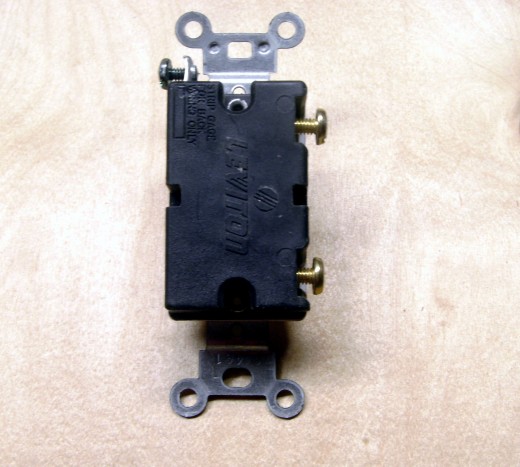
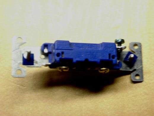
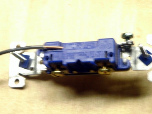
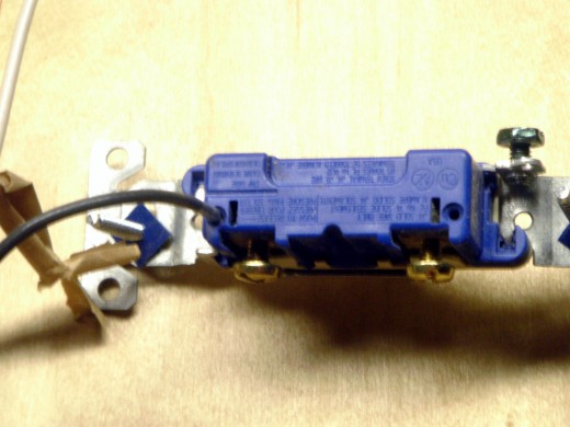
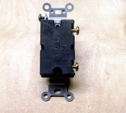
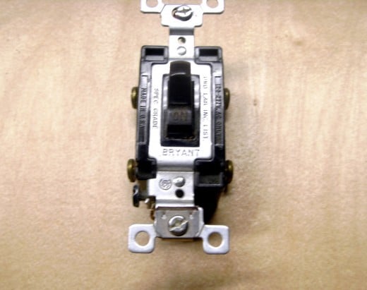
There are two general methods of physically attaching the wires to the switch. Most 15 amp switches (to be used only on a 15 amp circuit with a 15 amp fuse or breaker) will have both screws on the side and small holes on the back. Wires may be stripped of insulation for about ½ inch and bent into a half circle, put under the screw head and the screw tightened or the insulation stripped to the proper length (there is a strip gauge on the back of the switch) and pushed into the holes where a spring will hold them. As an electrician I won't use the holes as the springs inside that hold the wire eventually weaken and make a poor connection (resulting in not only a light that won't work but a definite electrical fire hazard as well). The screws used for these two wires are typically the larger two, are a brass color and are located on the side of the switch.
A third screw, typically located near or on one end, is intended for the ground wire and is often colored green. It is normally obvious that this screw is connected to the metal framework of the switch instead of going through the plastic side. Every switch must have a ground wire attached; the only exception is for older homes that do not have ground wires in the switch box.
With the wires attached, fold the wires back into the box and push the switch in as well. Two screws hold the switch to the box; tighten firmly but not so tightly that the screw strips out the plastic of the box and won't hold any more. Attach the cover plate with a single screw in the center.


Wiring Other Types of Electrical Switches
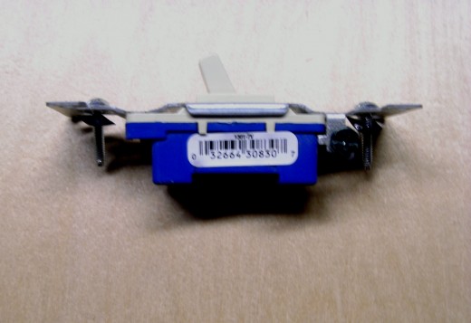
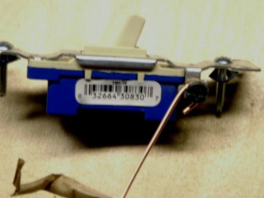
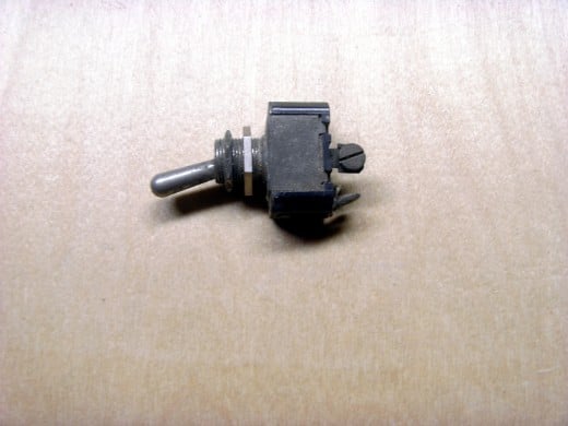
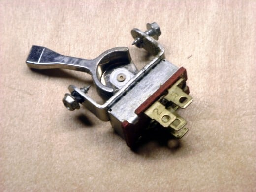
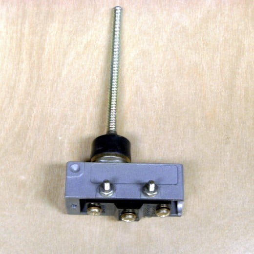
As mentioned, there are literally thousands of different types of electrical switches, from giants 6 feet tall to micro switches not meant to ever be touched by human hands. One switch might have 20 or more positions with 20 different results. Or it might operate 10 different devices, each with it's own circuit, all at the same time. Just a very few possibilities are shown in the photos below, with a brief explanation. Switches can be momentary contact, turning on (or off) only while held in position or maintained contact, remaining in the same position until manually switched on or off. Or it might be timed - turn it on and it remains on for 10 minutes and turns off (a bathroom heat lamp perhaps).
The actuating force might be a human hand, a moving box on a conveyor line, a gust of wind or even a light beam. It might be a pressure switch, turning on a well pump or air compressor when pressure falls and turning it off when the pressure is high enough.
In every case, though, incoming current is either turned on or off and this means that there is a line wire (a wire with constant power on it) and a load wire (a wire that is switched on and off) to be attached. The vast majority of switches don't care whether the line or the load wire goes to which terminal, although a few do. A lighted switch placed inside a home that lights up when the garage light is turned on for instance, would stay lit all the time if the line wire was put to the wrong terminal. Some switches light up when turned off in order to see them in the dark, and wire placement will matter here, too.
In such cases, try to follow the directions with the switch, particularly if the switch needs a white neutral wire to operate it's internal light. That neutral wire must go to the proper terminal! If the line and load wires are inadvertently reversed, though, no damage is done; if an internal light doesn't work as expected simply reverse the wires and try again.
Different Types of Electrical Switches
Click thumbnail to view full-size


© 2012 Dan Harmon

