A Case Study in IP Telephony Implimentation
Published: December 12, 2011
Short Link
http://hubpages.com/t/2b22ce
This case study illustrates the pitfalls of the Eastern Ohio Planning Corporation (EOPC)’s conversion from a traditional Public Branch Exchange (PBX) phone system to IP Telephony (IPT). The author’s purpose was to help engineers instill the importance of requirements gathering on sales associates who provide IPT solutions to their customers. The pitfalls encountered in this project could have been avoided by using proper requirements gathering and project planning techniques.
Some roadblocks faced by the implementation team originated because the initial design team left the company without providing a knowledge transfer and this situation required the implementation team to redesign the network during the implementation phase of the project. Documenting the discovery phase of the project would have eliminated this roadblock. The pitfalls that this paper covers include the following: Virtual Private Network (VPN) connections, a bridging-loop, Power over Ethernet (PoE), and the Dynamic Host Configuration Protocol.
The author addressed these pitfalls and the workarounds of the implementation. The intended audience of this paper comprises the following group of people with varying levels of expertise in the IT industry: the course instructors, fellow students, and network engineers. Providing background information on IPT will aid those individuals who are not familiar with the topic to understand the content of this paper.
Assumptions
This case study was tailored toward an audience whose members have varying degrees of experience in Information Technology (IT). For the purpose of the case study, the author makes certain assumptions about the technical understanding of this audience. These assumptions include the following:
- Readers of this paper should possess a basic knowledge of networking-technology.
- Readers of this paper should understand the basic concepts of the Transmission Control Protocol / Internet Protocol (TCP/IP).
Detailed explanations of basic concepts are beyond the scope of this case study. The author changed the name of the company involved in the actual implementation in order to protect the anonymity of those involved.
What is IP Telephony?
“VoIP is a generic term for using IP data networks like the public Internet to transmit voice traffic” (ShoreTel, 2005, p.3). Early Voice over Internet Protocol (VoIP) systems required the user’s PCs to be equipped with sound capability and a software application to convert speech to digital packets suitable for transmission using TCP/IP as the transport mechanism. The disadvantages of these early systems were poor voice quality and system incompatibility. Both parties of a conversation needed to use the same software application.
VoIP has evolved and the sound quality is now acceptable for commercial applications. Service providers like Vonage offer VoIP services to subscribers for a reasonable price. (Vonage Marketing, Inc., 2007). These services permit subscribers to initiate an unlimited number of long-distance phone calls for a set monthly fee. The Analog-to-Digital (AD)conversion occurs at the customer’s premise and the packetsare transported over the provider’s private network using the TCP/IP protocol.
When the receiver of a VoIP call is also a subscriber to a VoIP service the call is transmitted digitally end-to-end. When the receiver of a call is not a VoIP subscriber, the call goes through a Digital-to-Analog (DA) conversion process to convert the call back to a voice transmission suitable for a Plain Old Telephone Service (POTS) subscriber. Most residential non-digital phone services use the POTS infrastructure. The DA conversion takes place at the egress-port of the provider’s network located at a Point Of Presence (POP) where the call integrates with the Public Switched Telephone Network (PSTN).
VoIP leverages a reduction in long-distance charges, whereas “IPT uses a private IP network for voice calls, not the public Internet. IPT provides organizations with the ability to leverage their existing private IP data networks to transport voice traffic” (ShoreTel, 2005, p.3). The principles of digitizing conversations are the same but the premise equipment is different for IPT compared to VoIP.
The IPT implementation presented in this case study required the addition of phone switches and a voice server to the existing Ethernet network. The phone switches control the connections between individual phone handsets and the outside PSTN network or between two or more internal handsets for calls within an organization. The voice server is a file server loaded with software configured for phone operations like voice-mail and control functions like auto-attendants and handset assignment.
Network requirements of IP Telephony
The two main requirements for IPT are enough bandwidth to handle call volume and acceptable latency times. According to ShoreTel (2005), on Local Area Network (LAN) circuits with high bandwidth availability 82Kbps may be used. Low bandwidth Wide Area Network (WAN) connections may only take up 28Kbps.
Latency is the time from mouth to ear. It is the time it takes for a person’s voice to be sampled, packetized, sent over the IP network, de-packetized and replayed to the other person. Distance alone on the WAN circuit can cause delay, as can lower-speed WAN circuits. If latency is too high, it interrupts the natural conversation flow, causing the two parties to confuse latency for pauses in speech. Latency must not exceed 100 milliseconds (ms) one way for toll-quality voice and must not exceed 150 ms one way for acceptable quality voice. (ShoreTel, Inc., 2005, pp.3-4).
According to McIntire (2002), getting good quality of service from VoIP is the greatest challenge because data networks were not intended for or designed to meet the constant steady- stream demand that VoIP conversations require.
Analysis of the EOPC Existing Network
Describing the EOPC existing network is necessary to introduce the required changes to the network and analyze the pitfalls of the implementation.
Existing Phone System
According to the EOPC Director of IT, the EOPC does not own a phone system and operate on a Centrex system located at the phone company’s Central Office (CO). The Centrex system is an alternative to the PBX systems employed by many organizations. The advantage of a Centrex system is that no local staff-members are needed to administer the system. The disadvantage is the expense. The EOPC leases the system and lines from the phone company and must also pay for the administration and maintenance of the system. There is also at least one CO line connecting to each of the remote locations and some Direct in Dial (DiD) lines to all EOPC locations for fax machines and some personnel.
Local Area Network (LAN)
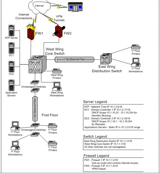
All the file servers on the current EOPC network connect to the network through the West Wing Core Switch, which comprises the main focal point of the network. The East Wing Distribution Switch connects to the West Wing Core Switch using a 1 Giga-bit (Gb) fiber connection. Figure 1, the EOPC Pre Deployment Network Diagram in Appendix C provides an illustration of the connections. There are also two unmanaged access switches on the first floor of the Hamilton Building, the organizations headquarters, that daisy-chain together and connect to two other unmanaged switches in the IT Director's office over another 1Gb fiber connection. There is then another 1Gb fiber run to connect this collection of unmanaged switches to the West Wing Core Switch.
IP addresses throughout the organization reside in the 10.1.0.0 network. This addressing structure is best described as a flat network because there is no network segmentation. All devices connecting to the network share the same broadcast-domain. The West Wing Core Switch and East Wing Distribution Switch are Layer-3 switches and possess the ability to segment the network but this ability has not been taken advantage of.
Metropolitan Area Network (MAN)
Eleven remote locations currently connect to the EOPC main office using Virtual Private Network (VPN) connections. These VPN connections terminate into firewalls at each of the remote locations and originate from a firewall in the Hamilton Building. Internet connections provide tunnels between the remote-location and main office firewalls so all data between these locations travel across the tunnels. The firewall at the main office also acts as the default gateway for network connections throughout the organization which means that all data flowing across the network flows through the VPN firewall.
Appendic C
Required Network Changes
Dynamic Host Configuration Protocol (DHCP)
The Dynamic Host Configuration Protocol (DHCP) provides a framework for passing configuration information to hosts on a TCP/IP network. DHCP is based on the Bootstrap Protocol (BOOTP), adding the capability of automatic allocation of reusable network addresses and additional configuration options. (Dorms, 1977, p.1)
A DHCP server answers requests from clients and provides them with configuration information, normally comprising the IP address for the client, the default gateway, DNS servers, timeservers, and so on. The EOPC presently uses two DHCP servers and supplies IP addresses using two address scopes. The two existing scopes follow:
- 10.1.15.10 to 10.1.15.254 /24
- 10.1.16.1 to 10.1.16.254 /24
New DHCP scopes are necessary to isolate the voice and data portions of the network. There will be one global voice network and a number of smaller networks for the departments and remote locations that access the network, however, only the voice network will be added as part of this implementation. The Director of IT has designated a new Novell Netware server to service the new scopes.
Managed Ethernet Switches
Inexpensive Ethernet switches can save money for small organizations that do not require the control or features of manageable Ethernet switches. However, applications like IPT include requirements that most unmanaged Ethernet switches cannot fulfill. The EOPC requires managed Ethernet switches and will upgrade some hardware. The two unmanaged switches on the first floor should be replaced and the two unmanaged switches in the Director of IT’s office should be eliminated. Quality of Service (QoS) filters are necessary to ensure voice quality and POE service is required to power the handsets, these two features are not available on unmanaged Ethernet switches.
T1 Pri Lines
The EOPC is replacing the existing Centrex system with the new ShoreGear IPT system and this change will effectively isolate the EOPC from the rest of the world unless the connections to the Centrex system are replaced. The EOPC has contracted with a local cable provider to supply two T1 Primary Rate Interface (PRI) lines.
Fiber Optic Trunks
The addition of IPT will increase the amount of data flowing between the East-wing and West-wing switches. To accommodate the increased traffic a second 1Gb fiber link should be installed between the switches in the East and West wings. The installation would also require the purchase of two additional Giga bit interface card (Gbic) modules to accommodate the additional fiber connection. The new fiber would aggregate with the existing fiber connection to double the available bandwidth. This aggregate-link should provide enough capacity to accommodate both the voice and the data traffic between the two wings.
Virtual Local Area Network (VLAN)
Although VLANs are not a requirement of IPT as offered by ShoreTel, EOPC has opted to incorporate a VLAN component in the network upgrade. A VLAN strategy has been developed to separate the voice and data networks as well as segment the organization by department. However, implementing VLANs other than that necessary for the voice component is outside the scope of this project.
ShoreTel; the EOPA System of Choice
The ShoreGear Voice Switch is the heart of the system and controls the operation of the phones. These switches support three different configurations depending on the number of users. The EOPC purchased two of the ShoreGear 120/24 switches and three of the ShoreGear 40/8 switches. According to Rash (2006), these switches will each support IP users in a ratio of one analog user to every five IP users with the larger number being the number of IP users. The EOPC plans on a few analog lines in scattered remote locations for backup purposes so these switches should support the 250 current users
According to Bassert, (2006),ShoreTel innovatively built redundancy into their IPT systems from the very beginning. In the IPT market, the concept of N+1 redundancy is exclusive to ShoreTel. N+1 redundancy means that whatever the requirements are for an application, one extra switch will provide a redundant fail-over solution. Every Switch in the system contains the same configuration as every other switch and the remaining switches will pick up the load if any switch fails.
Pitfalls
Remote Location VPNs
As stated earlier, all the remote locations communicate with the EOPA headquarters over VPN connections. Maintenance agreements on the firewalls that support the VPN connections was permitted to expire and no upgrades have been applied to the firewalls.
Problem
On October 24, 2007 the inbound phone connections to the Hamilton Building were transferred from AT&T to Lucky Cable, the new phone service supplier. The connection to one of the remote locations was also transferred at that time by mistake and cannot be transferred back. The existing VPN connection will not pass the new voice-traffic and the site has been without phone communication since October 24, 2007.
Solution and Prevention
According to Watchguard, Inc., the manufacturer of the firewalls, the firewall in the Hamilton Building is too old to support the voice protocol used for IPT communications. (Watchguard Technical Support, personal communication, October 24, 2007). Two POTS lines were added to the remote location on November 7, 2007, by Lucky Cable to temporarily restore voice communications. A replacement firewall has been procured and will be installed on November 12, 2007 to build voice-compliant VPN connections to the remote facilities. The tentative solution has not been tested.
This pitfall could have been prevented by determining the capabilities of the VPN connections between the Hamilton Building and the remote locations before the new phone-service connections were provisioned. IPT compliant firewalls should have been included in the initial proposal or service to the remote locations should have been left out of the new system proposal.
First Floor Bridging Loop
Problem
Wiring on the second floor of the Hamilton Building was installed in a manner that dedicated a wall jack to each computer and a separate wall jack to each phone on the floor. Configurations for these locations were simple because the computer and phone at a location would boot up on the native VLAN. No computers on the second floor were daisy-chained to IPT handsets and the phones on the second floor appeared to operate normally.
Daisy-chained phones on the first floor would not boot and the problem appeared to be an issue with DHCP until a protocol-analyzerwas connected to the network on October 18, 2007. The true problem turned out to be a bridging-loop. Refer to Figure 2, the Bridging Loop Diagram, for an illustration of the following bridging-loop description:
A phone attaching to port 3 of the hub powers up and issues a DHCP request. The hub relays the request out every port with a connected device except for port 3 where the request was received. First-floor switch A receives the request on ports 1 and 24 because they both connect to the hub so the switch forwards the request out every port with a connected device, including ports 1 and 24, because the DHCP request is a broadcast.
Internally, the switch forwards the request received on port 1 out port 24 and the request received on port 24 out port 1. This loop would continue until the switch looses power except for a mechanism called the Time To Live (TTL). The TTL starts with a value of 255 and decreases by a value of 1 each time the switch receives the same request. When the TTL decreases to a value of 0, the switch ceases forwarding the DHCP request.

While the request loops around the hub and switch A, the request has successfully reached the DHCP server and the server answers the DHCP request with a DHCP offer. The initial DHCP offer does not reach the phone, however, because the looping request between the hub and switch A block the offer. After a short time, the DHCP server retransmits the DHCP offer because the server receives no acknowledgement from the phone.
The DHCP offer is caught in the same type of looping condition that the DHCP request experienced. The DHCP server continues to make offers and continually fails to receive an acknowledgement from the phone until a mechanism within the TCP/IP stack forces the DHCP server to stop making the offers. The phone actually receives the offers but the looping activity prevents the phone from successfully acknowledging to the server that an offer was received.
Solution and Prevention
The preceding phenomenon is known as a broadcast-storm and has been observed to occur whenever a phone on the first floor of the Hamilton Building is powered up. Phones that connect directly to the West-wing switch occasionally powered up successfully but sometimes also failed because of the broadcast-storm.This problem was resolved on October 30, 2007, when a wireless access-point was discovered and disconnected from the network.
Preventing this problem from occurring would have been a simple matter if a detailed network map that accurately depicted the EOPC network existed. The offending access-point would have easily been located on the map as a possible problem.
Dynamic Host Configuration Protocol (DHCP)
Problem
The EOPC implemented a new Novell Netware server to handle DHCP transactions for the new implementation and eliminate the two existing DHCP servers operating on DC1 and DC2, see Figure 1 the EOPC Pre Deployment Network Diagram in Appendix C for server locations. The new server was placed into service before the existing servers were decommissioned and phones did not acquire IP addresses in the correct subnet range. This led the team to believe that the new DHCP server was not functioning.
Solution and Prevention
A specialist was called in to help isolate the bridging-loop problem and he discovered that the phones were actually receiving IP addresses from the scopes provided by the existing DHCP servers. The new DHCP server would not answer the requests because they came from sources that the new DHCP server was not responsible for. Eliminating the DHCP option from the configurations of the affected phones and configuring those phones manually permitted the new DHCP server to age out the addresses in three days and the phones were able to auto-configure, boot up, and operate normally. Completing the DHCP upgrade before implementing the new system would have prevented this problem.
Power over Ethernet
Phones require power, whether they connect to a POTS line, a PBX, or an IPT system, they must obtain power from a power-source. Phone companies deliver power to phones over the phone lines, as do PBXs. IPT switches, however, do not connect directly to the phones; an Ethernet switch intervenes. This means that an IPT phone must obtain power from either the Ethernet switch that connects the phone to the network or from a power-injector. A power-injector draws power from a standard power outlet, which is a disadvantage as is the space the injector occupies. The new Ethernet switches in the Hamilton Building are POE compliant and the EOPA planned to power the IPT handsets in the Hamilton Building using those switches.
Problem
The West Wing Core Switch and the East Wing Distribution Switch, see Figure 1, EOPC Pre Deployment Network Diagram in Appendix C for switch locations, were underpowered and the switches would stop supplying power to handsets after 21 handsets were connected to the switches.
Solution and Prevention
Adding a power supply to the West Wing Core Switch and the East Wing Distribution Switch solved the problem by supplying the additional power. Although adding additional power supplies easily solved the problem, the expense involved was cumbersome for a small organization like the EOPC and should have been included in the original-equipment purchase for budgeting reasons. Determining the power requirements for the IPT handsets and including the additional power supplies in the system requirements for the new IPT system would have prevented this problem.
Conclusion
Proper planning and design are crucial to the successful deployment of any new system. Many of the pitfalls of the EOPC IPT deployment were preventable by using proper information discovery and requirements gathering techniques before the sale of the IPT system. This implementation essentially moved from closing the sale to deploying the equipment.
Engineers should instill a sense of urgency to complete information discovery and requirements gathering activities on sales associates who supply IPT solutions to their customers. The pitfalls of the EOPC IPT implementation demonstrates this need and engineers should be prepared to assist in these activities when called upon.
The EOPC implementation team was required to redesign the network while deploying the new phone system, which is an unacceptable situation The discovery phase for an IPT project should identify and address the following concerns:
- the scope of work for the project
- availability of a complete and accurate map of network topology
- whether configuration protocols are static or DHCP
- power requirements of the IPT system
- proposed power sources and capabilities of those sources
- types of connections to remote locations and their limitations
- competencies of the implementation team
Properly addressing these concerns would have eliminated the deployment pitfalls at the EOPC that required additional product purchases and added deployment time. There is no excuse for the VPN deficiencies at the remote locations not being discovered before the voice communications to one of those locations was lost. Some of the pitfalls requiring additional configuration time are attributable to the unfamiliarity of the deployment team with some of the new equipment, specifically: the Novell Netware DHCP server.
References
Basart, E., (2006). Building reliable IP telephony systems: how architecture and design differentiate ShoreTel from the competition. Available from http://www.shoretel.com
Dorms, R., (1997). Abstract [Electronic version]. Request for Comments: 2131 Dynamic Host Configuration Protocol. Internet Engineering Task Force. Retrieved October 26, 2007 from http://www.ietf.org/rfc/rfc2131.txt
Rash, W. (2006) Easy management makes ShoreTel PBX a delight [Electronic version]. Infoworld, 28, 2 p36-39. Available from the EBSCOhost database
Vonage Marketing, Inc. (2007). Simple to set up. Simple to save. Available from http://www.vonage.com
Appendix A
Project Proposal
Date: November 17, 2011
To: Accepting Authority
From: Dumbledore
Subject: Project Proposal for a research paper detailing the case study of an IP
Telephony Implementation
Introduction
Voice over Internet Protocol (VoIP) is typically a commercial offering aimed at reducing long distance charges by transporting phone conversations over digital networks like the public Internet. IP Telephony (IPT) uses the same type of technology as VoIP but aims to replace internal phone networks like those serviced by a Public Branch Exchange (PBX).
Problem
Value added retailers and consulting firms may sell an IPT solution without any knowledge of the requirements of IPT or whether the infrastructure that will support the solution meets those requirements. Lack of documentation of the existing network and processes that the new solution will affect compounds this problem.
Proposed Solution
I propose writing a paper to document the pitfalls of one such installation: The implementation of IPT for the Eastern Ohio Planning Corporation (EOPC). Writing this research paper targeted toward people with varying degrees of familiarity with general IT principles and little knowledge of IPT should help readers gain the knowledge to conduct successful information and requirements gathering investigations before implementing the IPT technology. This research paper will address the following:
- briefly explain VoIP and IPT
- provide an analysis of the EOPA existing network
- introduce the selected IPT system
- explain the necessary changes to the existing network infrastructure
- Describe the various encountered pitfalls and their solutions
- Provide some basic guidelines for discovery before the sale of an IPT solution
Timeline
The deadline for completing this paper is November 30, 2011. Figure 1, Gantt Chart for the IPT Conversion Project, illustrates the project tasks and dates for completion. Four milestones represent tasks that are crucial to completing this project and comprise the following: (a) Submit Final Outline, (b) Submit Final Project Proposal, (c) Final Progress Report, and (d) Final Project Submission. The dates for the completion of these tasks can be extruded from Figure 1.
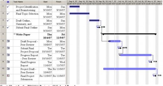
I have completed the first eight tasks, although I must revise my Project Proposal for inclusion in the final paper.
Work Completed
I have gathered most of the research material for this project and am involved in daily communications with the EOPA Director of IT who is supplying much of the information detailing the organizations existing network and future plans. I have written the introductory material on IPT and am presently concentrating on the problem areas of the implementation and developing a glossary of terms. I have also designed a table describing the new VLAN structure. Two of my illustrations are complete: the existing network diagram and an illustration of a bridging-loop.
Set Backs
I seem to be spending more time than I would like developing the glossary. Background information was occupying more space in the body of the paper than what the overall length of the paper would require because I was oversimplifying some concepts. The glossary is a tool to help cut down on the length of the paper. Stating some basic assumptions in the beginning of the paper should also help relieve the problem of writing too detailed an account to fit the page requirements.
I am also suffering from a case of writer’s block when I try to describe the existing network infrastructure. I have the information needed to create a VISIO diagram and the visualization that the diagram will provide should relieve my writer’s block.
Moving Forward
I will complete work on this paper in the coming weeks. This weekend I will complete the aforementioned VISIO diagram, which should remove my largest obstacle: The verbal description of the existing network.
The two remaining tasks for the project following the submission of this progress report can be seen in Table 2, Remaining Case Study Tasks:
Conclusion
Working on this paper as I struggle through a major technology implementation has strengthened my position on the importance of solid requirements gathering and project planning. This paper could be a valuable resource to those considering the deployment of IPT in their organizations by demonstrating that you must gather the facts before you begin and plan for the unexpected. Although I am a little behind schedule, I will meet the deadline of November 9, 2007, through proper diligence of writing.
Please post any comments you may have to the appropriate message thread. I will be very excited to read your comments and suggestions. I will be checking daily for any input.

Progress Report
Date: November 3, 2007
To: Accepting Authority
From: Dumbledore
Subject: Progress Report of Case Study Project
Summary
On October 13, 2007, I finalized a proposal to write a research paper detailing the pitfalls of the IP Telephony implementation for the Eastern Ohio Planning Corporation. The agreed purpose of the paper is to educate readers on how to avoid the roadblocks to these types of implementations through proper planning. I will provide background information regarding IPT but the focus of the paper will lean toward avoiding the pitfalls through proper planning.
I developed a project plan for this paper comprising 10 tasks for completion as detailed in Table 1, Tasks for Case Study Completion:

Expected Results
Readers of this paper should acquire a general knowledge of VoIP and IPT. An analysis of the pitfalls encountered by the author and the solutions to those pitfalls should aid those readers in planning the discovery phase for future projects.
Conclusion
The successful deployment of IP Telephony requires proper planning just like any other project. This proposed paper will document the pitfalls of an implementation that demonstrates the need for information and requirements gathering activities. This paper should provide the reader with adequate knowledge to develop a strategy to avoid some of the pitfalls by discovering the capabilities of an existing network before the sale of an IPT solution. This proposed paper will be completed and submitted by November 9, 2007.


