Basics of Strain Gauging


If a conductive metallic band is pulled and stretched from both ends, it will become longer and slenderer. Both these changes bring about an increased electrical resistance throughout the band. On the contrary, if this conductive metallic ribbon is applied compressive force, it will become short and wide. If these forces don’t go beyond the elastic limit of the band of conductive metal (so as not to permanently change its shape), the band can be utilized as a measuring tool for physical force, i.e. by measuring the resistance it applies against the applied force and thus inferring the amount of the force. And this type of device is known as a strain gauge.
Strain gauges are commonly used in research and development in mechanical engineering to measure the stress produced by machinery. Testing of aircraft components is an area of their application too, where small strain-gauge strips are glued to linkages, structural parts and any other crucial components of an airframe to determine stress. In most cases, strain gauges are smaller even than a postage stamp and appear somewhat like this:

The conductors of a strain gauge are extremely thin, i.e. their diameter is around 1/1000 inch if made of round wire. They also may be in form of thin metallic films dumped on a nonconductive material acting as a substrate called carrier.
Bonded gauge is strain gauge that is glued to a bigger structure under stress (known as test specimen). The bonding of strain gauge to test specimen may seem easy, but it’s not. “Gauging” is quite a skill, extremely essential for getting exact, steady strain measurements. Though it is possible to measure tension with the help of an undeposited gauge wire kept stretched out between two mechanical points; but the method has its limitations.
Strain gauge resistances typically range between 30 Q and 3 kQ (unstressed). This amount may differ only by a fraction of a percent for entire range of force of the gauge, provided the limitations posed by the elastic limits of the test specimen and gauge material. Forces which are higher enough to evoke higher resistance differences would distort the gauge conductors themselves and/or test specimen, thus damaging the gauge. Therefore, we should absolutely small differences in resistance with great precision to use the strain gauge as a sensible measuring device.
With this basic knowledge of strain gauging we’ll now see what are the uses of strain gauging and where is it applied commonly.
Strain gauge is a very important tool of the electrical measurement method used to measure mechanical quantities.

Bonded Foil Type of Strain Gauge
The first of this kind of metallic foil-type strain gauge was created in 1938. The metallic wire-like strain gauge contains a mesh of wire filaments (a resistor) of about 0.025 mm (0.001 in) of thickness, bonded straight to the strained surface using a thin sheet of epoxy resin. If a weight is applied to the surface, the resistor is communicated of the resulting alteration in surface length and the consequent strain is measured in form of the electrical resistance of the wire foil, that differs linearly with strain. The foil diaphragm and the bonding material should work with each other in sending out the strain, while the bonding material should also act as an electrical insulator between the surface and the foil grid. While choosing a strain gauge, you should not only consider the sensor’s strain properties, but its temperature sensitivity and stability too. Unluckily, the most appropriate strain gauge substances are sensitive to temperature changes and are inclined to show changes in resistance with age. This may not be a big concern for short duration tests, but for ongoing industrial measurements, you should include temperature as well as drift compensation.
Bridge Measurement Circuit
Because of the need of high accuracy there is a requirement of a bridge measurement circuit. A strain gauge bridge measurement circuit shows measured strain by the amount of imbalance and utilizes an accuracy voltmeter in the middle point of the bridge to give a precise measurement of the imbalance.
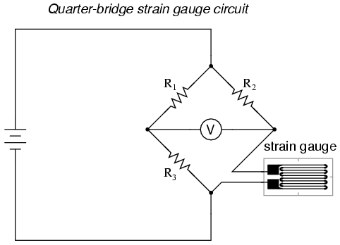
Characteristically the rheostat arm of the bridge (R2in the figure) is set at a digit equal to the strain gauge resistance without any applied force. The two ratio arms (R1 and R3) are made equal to one another. So, without any applied force to the strain gauge, there will be a symmetrical balance in the bridge and the voltmeter will show zero value, signifying zero force on the strain gauge. Since the strain gauge is either tensed or compressed, its resistance will increase or decrease, respectively, thus making the bridge imbalanced and forming a signal at the voltmeter. This system, with only one element of the bridge altering resistance responding to the measured variable, is called a quarter-bridge circuit.
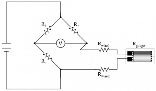
Because the distance between the three other resistances and the strain gauge may be sizeable, wire resistance has a considerable impact on the working of the circuit. The same diagram has been added two resistor symbols serially with the strain gauge to signify the wires.
Custom Strain Gauges
Custom strain gauges can be formed to ease out strain gauge installation when space is limited or for a particular application. Customization of strain gauge can bring about:
- Modification of a typical gauge pattern
- Form a custom gauge pattern
- Place many gauges on one single carrier
- Offer non-standard length of the lead
- Custom material
- Offering extra wiring points or relocating solder pads
- Form particular trim shapes or dimension to clear hindrances
Types of Strain Gauges
Four main types of strain gauges are seen in the industry:
- Mechanical
- Hydraulic
- Piezoelectric
- Electrical

Mechanical
This can be understood by an example of a crack in a wall which you want to know if worsening. When you call in the building inspectors, they glue a piece of hard, plexiglass plastic marked with a scale and lines straight over the crack. This is sometimes called a crack monitor. You will see that it is in fact made of two individual plastic layers of which the bottom layer bears a calibrated scale on it and the top one bears a red pointer or arrow. You need to glue both the layers on either side of the crack, so that when the crack opens, the layers glide very slowly over each other and you can see the red arrow moving past the scale. Based on how fast your crack is widening, you can come to know what time you have to fix it and solve your problem.


Hydraulic Strain Gauge
The ability to detect only very small strains is a problem with strain gauges. If, for example, a house is subsiding slowly but the speed is so slow that it won’t show up, the damage is done already. Using a basic crack monitor as shown above a 1 mm of movement is shown if the building moves by 1 mm. So, what can be done when detection of movements smaller than this is to be done on a scale? In that case, a strain gauge having leverage that magnifies the strain is necessary so that even a slight movement can be detected in form of a much enlarged and easily detectable movement of the indicator on the scale. And here hydraulic strain gauge steps in. These work almost like syringes. Just as in syringes, hydraulic pistons bring about a large movement of fluid upon pressing of your thumb, hydraulic strain gauge have a large piston and a smaller piston of which the larger one is to be connected to the area that is producing strain and smaller strain is to be used in a smaller tube, calibrated with a scale, to show the amount of movement. The associated size of the pistons decides how much amount of movement you are trying to find out which is scaled up. Hydraulic gauges are used mostly in Earth science and geology.
Piezoelectric Stain Gauge
Some materials like various types of ceramics and quartz crystals are natural strain gauges. Upon pushed and pulled, they create small electrical voltages amid their opposite sides. This is known as piezoelectricity and it is perhaps the most famous as a means of giving the timekeeping indication in quartz watches. By measuring the voltage from a piezoelectric sensor, you can evaluate the strain very easily. Piezoelectric strain gauges are considered to be one of the most reliable and sensitive types of strain gauges and can stand years of constant use.

Electrical Strain Gauges
While designing a thing like an airplane wing, you typically require far more advanced measurement devices than a basic mechanical strain gauge. There is a need to measure the strain, for example, during takeoff, when maximum thrust is produced by the engines. In that case, you cannot stick the tiny plastic stain gauges over the wing and move out to measure the strain when the plane is in flight. Here, it’s the electrical strain gauges which do much the same job in the cockpit from a flight recorder.
The most commonly used electrical strain gauges are rectangular thin strips of foil having maze-like wiring designs on them causing two electric cables. You can stick the foil on the material you wish to measure and plug the cables to your monitoring circuit or computer. If the material you intend to study is strained, the foil strip is bent out of shape very slightly and the maze-like wires are pushed together or pulled apart. If the width of metallic wire is changed, its electrical resistance changes too, because it is difficult for electrons to pass electric currents through narrower wires. Therefore what you need to do is to measure resistance and eventually the strain gauge regains its original shape. Thus you can keep taking measurements for long, such as during a prototype plane’s flights.
This type of strain gauges was first discovered by MIT professor Arthur Ruge in 1938 to aid earthquake detection.


 Keep Tripping the Breakers?")


