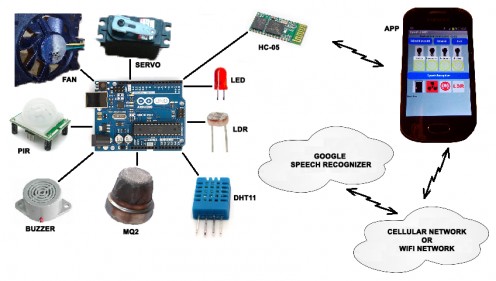
Details Of The Automation Home Schematic Diagram

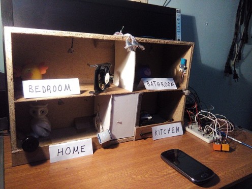
To achieve my goals in the development of the Automation Home with App Iventor 2 we can use several solutions both hardware and software, in my case I found the following solutions to develop this project simulator and I describe it below:
1. Fan
Through the cell application I activate and deactivate a relay to start the fan. In this case I use a transistor to amplify the pulse of the Arduino board and in this way I can power a 5V relay and that closes the circuit where the fan is powered with a 9 VDC source.
2. Servo
Through the cell application I activate and deactivate a servo that helps me open and close a door. When I press the key to open the door, then my servo turns from 5 to 180 degrees. When I press the key to close the door, my servo rotates 180 degrees to 5 degrees. Depending on the design you make with your door, it is how the degrees you can modify the source code will be. In a real situation I would use the servo to open and close the door lock unless it has a servo large enough and more torque to open and close the door.
3. PIR Motion Sensor
Through the cell application I activate and deactivate the "PIR Motion Sensor" that helps me activates a buzzer when it detects a strange human presence. In this case I am feeding the PIR and the buzzer with the same pulse voltage from the Arduino board and it was not necessary to feed them with an external voltage source. When the buzzer is activated, it sends a pulse to the transistor so that it in turn activates a buzzer with five volts. You can modify the distance and the time of the pulse by means of two potentiometers that the PIR sensor has.
4. MQ2 Gas Sensor
Through the "MQ2 Gas Sensor" I can detect gas leaks in the kitchen. This sensor is powered directly by the Arduino board and provides an analog voltage that depends on the amount of gas in the environment. The analog voltage is sampled at the analog port A0 and when it exceeds the value of 500 then it activates and blinks the kitchen LED and sends the data to the application of our cell phone.
5. DHT11 Humidity Sensor
Through the cell application I activate and deactivate the "DHT11 Humidity Sensor" that helps me measures the relative humidity and temperature in the bathroom. This sensor measures and sends the values to the cell phone application and we can see them in real time.
6. LDR Night Sensor
Through the application of the cell phone I activate and deactivate the "LDR Night Sensor" that I use to light the exterior lamps of my house when we find ourselves in total darkness. In this case I use a transistor to amplify the pulse of the Arduino board and in this way I can power a relay of 5V and that it closes the circuit that feeds several LED diodes with a 9 VDC source.
7. LED Light Illumination
Through the cell application I activate and deactivate the LED diodes which are being powered by the Arduino board. I am using LED diodes to simulate the lighting of a house's lamps: living room, bedroom, bathroom and kitchen. In a real situation we would use these pulses to activate lamps and depending on their technical specifications we would use different solutions. For example, if the lamps were less than 10 VDC then we would use the L293B driver, if the lamps were 110 VAC we would use relays.
8. Speech Recognizer
Through the cell application I activate and deactivate the "Speech Recognizer" which serves me to perform the same orders of the previous seven steps but using the human voice. The Speech Recognizer records the voice, digitizes it and sends it to a Google server which translates the audio and converts it into data or words. These words are returned to the cell phone application and I programmatically compare them with the words programmed to activate orders. You must have in mind that sometimes the voice is poorly translated and the order is not activated. To solve this problem I had to practice with several words until getting the best results even if grammatically is not correct. You can change these keywords in the code so that you have better results.
Next I show the keywords that I use and its meaning I put it to the right of each of them:
“home on” = open the door
“home out” = close the door
“bedroon on” = turn on the bedroom light
“bedroom out” = turn off the bedroom light
“bathroom on” = turn on the bathroom light
“bathroom out” = turn off the bathroom light
“kitchen on” = turn on the kitchen light
“kitchen out” = turn off the kitchen light
“door open” = open the door
“door close” = close the door
“fan on” = turn on the fan switch
“fan out” = turn off the fan switch
“Sound on” = turn on the PIR Motion Sensor
“Sound out” = turn off the PIR Motion Sensor
“light on” = turn on the LDR Night Sensor
“light out” = turn off the LDR Night Sensor
Note: If you want to analyze and / or modify the source code of this project, then I suggest you put the following in the google search: MIT App Inventor 2. You can access this site with a gmail google account and you can load the source code with extension aia to be able to start working with it.
Finally I have no more to thank your attention and patience to my document and I hope it is enough to satisfy your doubts and concerns about this project.


