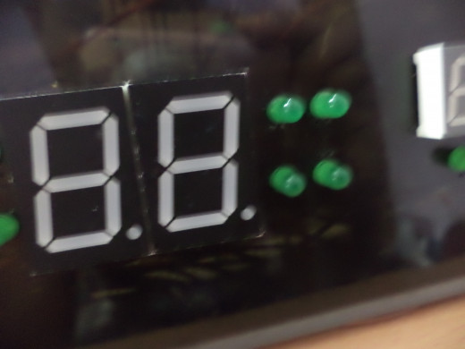
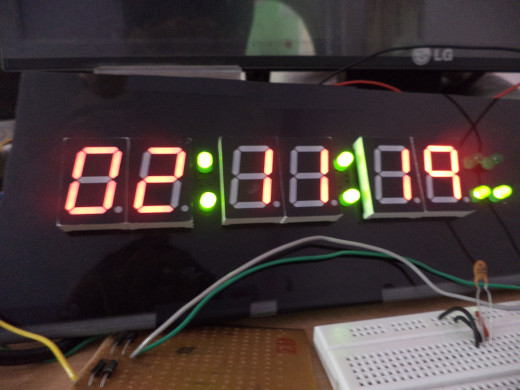
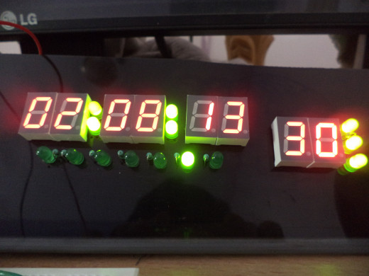
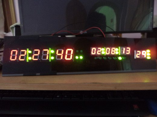
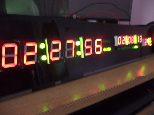
Digital Clock with Temperature Sensor DIY
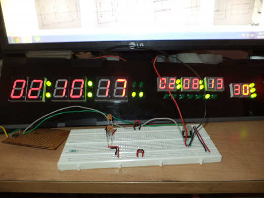
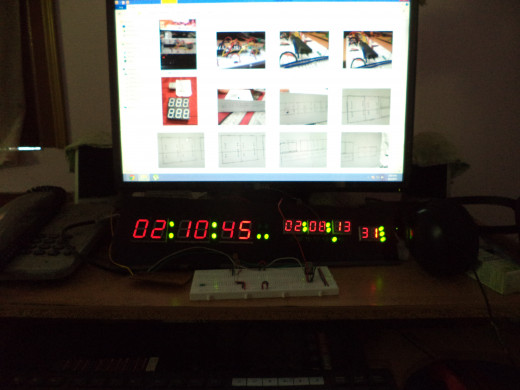
You can see in stores digital clocks laying around, but it’s too much fun to make one than just to buy. After that every time you look at your clock it will make you proud.
Everything from top to bottom is listed here, and every step what to do. If you still get stuck I will be there to help you.

What it will give you
1. Uninterrupted Time.
This means if your power is of for a few days, there is no need to reset you time, just like your computer. It uses the 3v extra battery to keep your time up to date.
2. Date with day.
Shows the day with help of 7 leds.
3. Temperature.
Uses LM35 temperature sensor for sensing room temperature.
What will you need
Mainly some small skills and some electronic components.
Skills:
- Little bit of idea about electronics.
- Soldering technique.
- PCB making skill (optional).
- Drilling skill.
Components:
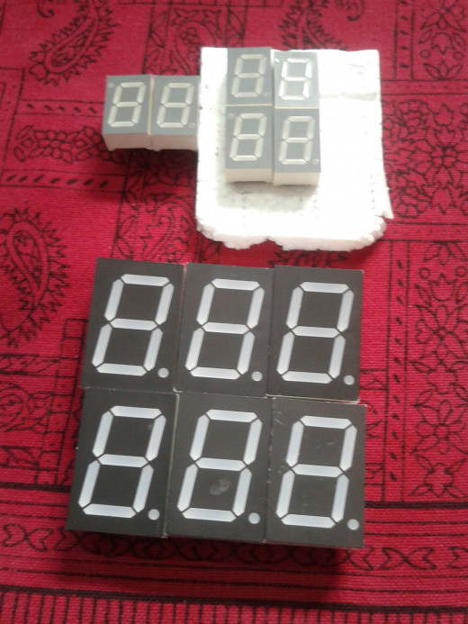
- 1 fiberboard depending on the size of your clock that you wish to make, mine was about 6 x 14 inches. Search for a thin and stiff one (3mm thickness max).
- ICs:
- ATmeag16.
- DS1307.
- 2 x 74HC138.
- 2 x CD4511.
- LM7805.
- Resistors:
- 1 x 10k.
- 15 x 100Ohms.
- 7 x 68Ohms.
- Capacitors:
- 8 x 0.1uF.
- 1 x 1000uF.
- 3 x 10uF.
- 2 x 22pF (optional).
- IC holder:
- 1 x 40pin.
- 1 x 8pin.
- 4 x 16pin.
- 3v Battery and its holder.
- Xtal 32.768KHz (One of the most important this controls the heartbeat of your clock, so make sure it’s a good one)
- 37 straight berg pins both male and female.
- Lots of colored wires, preferably at least 7 colors.
- Vero boards depending on your need. (I only used 5 small as my main board was on pcb).
- And the last but not the least, an avr programmer. You can buy one or build one, here are two links to build one:
- USB Programmer.
- Serial Programmer.
Simple Question
Why do you like electronics?
Finally the steps
There are few simple steps to success, it took me 1 month. Okay, actually I was lazy you can do it in about 1 week.


Step 1: Build the board
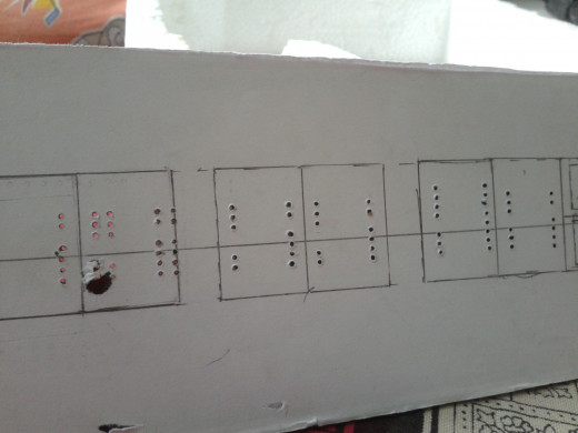
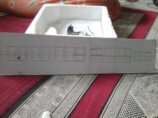
My chassis was on a fiber board, cut it in a desirable size you want. It is not necessary to stick to my design, design you own, be creative. So,
- Cut it out in a desirable shape.
- Glue a white paper on one side of the board.
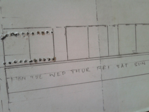
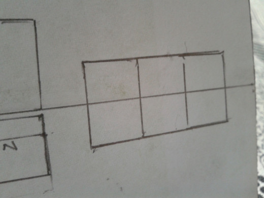
- Mark the shapes and sizes of you 7 segment leds, where you want to place it, by placing it upside down on the board.
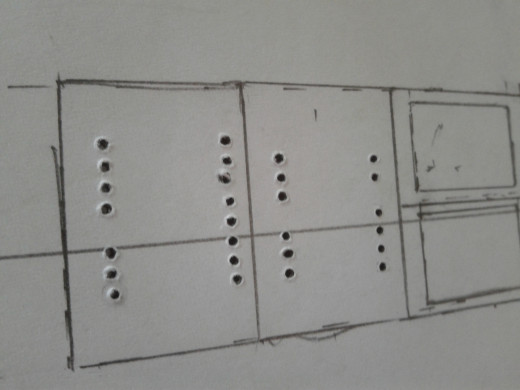
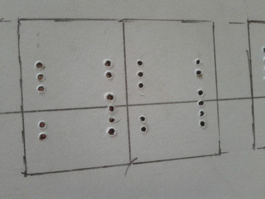
- Now take a vero board where your 7 segment led fits, and make marking on the hole where the pins of the display passes.
- Make markings on your vero board as per size your display.
- Place it on top of your fiber board and drill through the holes which of them were marked.
- Drill the holes for the leds in the same way, and remember the drill the holes for their resistor too (Use some desirable resistors there it may be from 60 Ohm to 300 Ohm).
It is stinky job, I know. Don’t faint if you make mistakes. I made many mistakes during this step, but those mistakes got hidden under the display.
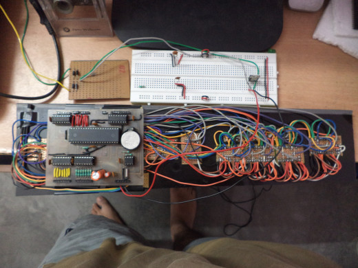


Step 2: Making the connections
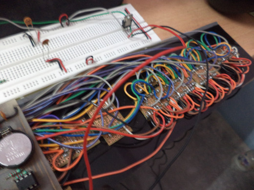
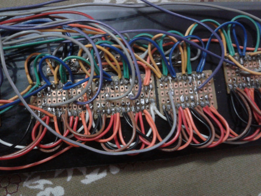
There are few simple steps, don't get afraid by the pictures. I know it's looking like some massive and complex wiring, but actually it's too simple and straight connections.
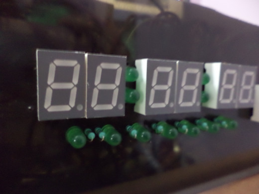
- Firmly put all the displays through the drilled holes.
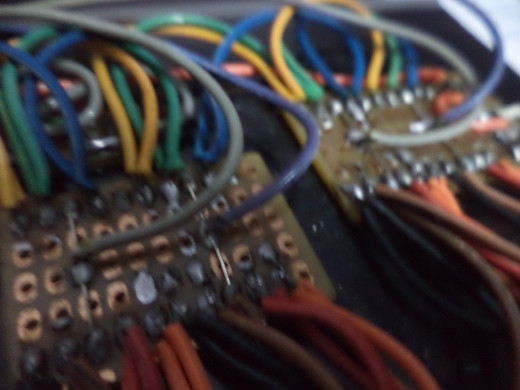
- Now cut the vero board as per required size and place it on the pins of the display on the other side of the board as shown in pictures.
- Solder the pins of all the displays.
- Now do the same for the rest of the leds and resistors.
- Make the connections, it is simple, if you see the schematics you will get to it.
This will take a little bit of time and patience, there are many pins where two wire emerge, so don't make the mistake of soldering one pin twice, just twist one pair of wire and solder it to the pin once.
Remember to use 7 different colored wirer for each segment, this will make your work a lot easier.
We will do the connection to the header later.
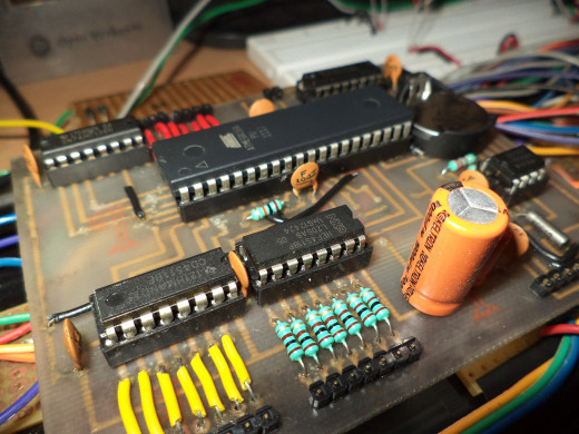


Step 3: Making the main board. The Brain
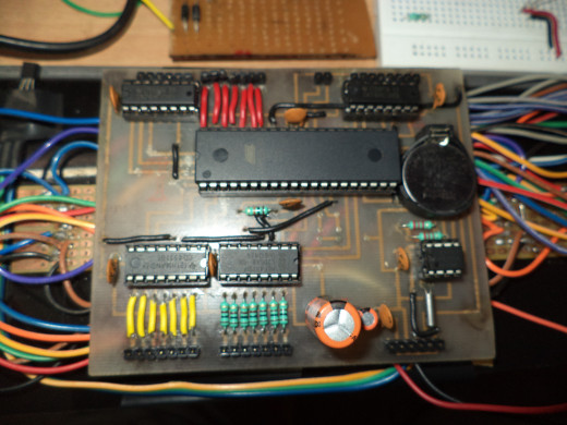
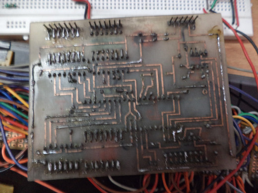
It is the most important part of this project, try to do it very seriously. I did it on a printed PCB made by me by the toner transfer method you can also do it on a vero board, it need to big (maybe 4 by 4 inches). Just make sure that its dimension is less than the fiber board.
- (Optional) Make the PCB by using my design or you can design your own.
- Place the components (IC Base, capacitors, resistors etc.), don’t solder the ICs you don’t want to get your microcontroller get burned.
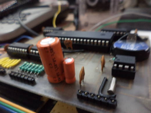
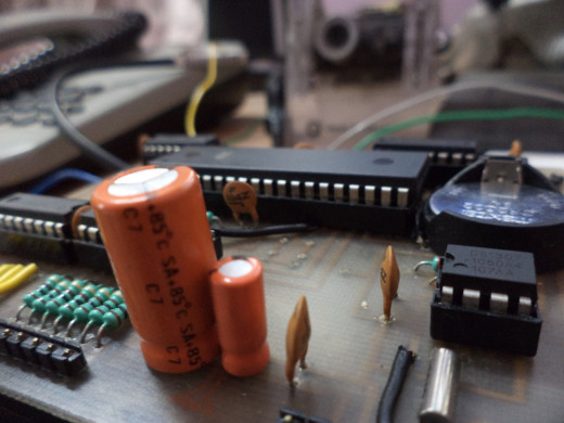
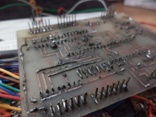
- Place your male berg headers on the other side of the board by using my method, you can see it on the images.
- Check your connections carefully.
NOTE: While putting the resistance in between the CD4511 IC, 100 Ohm resistance will not work always your display may get dim, you have do some experiment with it. As you see in the images I used no resistance between the first IC which controls my bigger displays (but that is not a good practice). Bigger displays will need less resistance than smaller one to make it look as bright as the other. But I think 100 Ohms between smaller one and 40 -60 Ohm will be perfect. If you are using the same size displays all over there’s no need to worry about this.
Done! Quick description but a long process. If you do it on a printed PCB things will be neat and you don’t have to do all the messy connections beneath it, but if you do it do it carefully, because mine was not so neat, I faced the problem of connection breakage when I debugging my code, it was really frustrating.
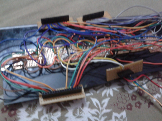
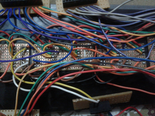
Step 4: Making the connectors
It is a simple step but needs concentration, you will need this headers for connecting your main board to the displays. You will need about 40 female header in this, be specific with female headers because we used male header on the board.
- Map your headers of the board.
- If you followed my PCB diagram you can divide your headers into 4 different parts and solder it to a vero board, just make that sure if the fits firmly side by side, so for safety first insert the female one to the males and the solder the females to the vero board. Or, if you made your own board just find a way to fit it on the fiber board just make sure that they fit and been placed firmly.
- Now take the help schematic diagram of the displays and connect the respective header to the anode pins of the displays, there will be 14 pins of these.
- Now time to connect the cathode pins, you have to know the pins of the IC 74HC138, see the image. The Y0 – Y7 is the selector pins, connect the cathode pins of the big displays respective from left to right to the selectors pins of first 74HC138 IC from Y0 to Y5. There should be 6 pins.
- Now by the same way connect the pins of the smaller display, there should be 8.
- Now the pins of the leds (AM, PM and day indicators) connect the cathode that is from the resistors to the respective headers.
- Connector the powers pins to the power supply.
We will take about powers supply and temperature sensor after this.
Do this step correctly by using the help of the pictures I provided if there is any problem you are always free to comment.
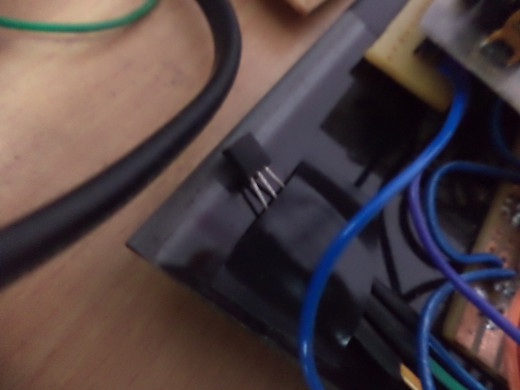
Step 5: Connecting the temperature sensor
It is a very very simple step.
- You can see the output pins for the temperature sensor in the main board, just connect those header by the side of the power pins to another 3 pin of female berg pins so that you can move your sensor anywhere and remove it any time.
Done! :-)
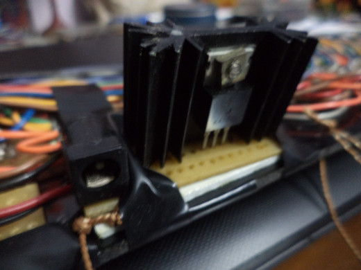
Step 6: Connecting the power supply
As you see the circuit there are two inputs of power. We have to supply the circuit exactly +5V, 1Amp. If you give a little less the displays will become dim, and if you give much more than that your microcontroller may blow up because they don’t like voltages above 5.5V. So you have to build a power supply and use a suitable to work properly.
- Place the components of the circuit of the power supply that I provided on a vero board and cut it down.
- Now solder the components on it and make the connections.
- Now for connecting it to the board you can use headers or you can connect it directly.
- Now place all the circuits (headers for the main board and power supply) with the help of Velcro or double sided tape.
NOTE:
You must use an adaptor of 12V,1 Amp rating don’t use less or more than that.
You must use a big heat sink for the LM7805 IC as it is not an LDO it will produce a hell lot of heat, and it is required for supplying 1Amp current to the circuit.
Though it is a digital circuit it does many switching jobs between few microseconds so eventually if you don’t give the required current to the circuit it will become dull.
Step 7: Programming the microcontroller
It is like teaching the circuit how to work. As all the hardware jobs done now time for the software. You will need some of the extra things to do this like a breadboard and a avr programmer. If you followed my whole tutorial and did all the things what I have done then you will be burn the firmware directly to the microcontroller or tweak with my code to match your own circuit.
- Buy a avr programmer. Like USBasp.
- Learn to program a avr by following this site. Site: NewbieHack
- There are several files in my firmware, if you are using programmer’s notepad then copy and paste the whole of Digital_Clock.c in a new project and save it.
- Now copy the rest of the file in the same folder where you saved it.
- Now open DS1307.c in notepad and uncomment the _ds1307_timer_initialization(); function by removing the two slashes before it.
- Now go to the end of that file you will see that there are field for date time and everything but it is in BCD format. You got to fill the time in that way like if the minute is 52 you have write there 0x52.
Example code: For 12th August 2013 Monday 11:27:00AM
  i2c_start_wait(DS1307_ADDRESS + I2C_WRITE);
  i2c_write( DS1307_SECONDS );
  i2c_write( 0x00 );          		//seconds
  i2c_write( 0x27 );         		//minutes
  i2c_write( 0x11 | 1<<6 | 0<<5 );      //12-hour mode, hours
//i2c_write(0x40 | 0x23 );   		//24-hour mode, 11PM
  i2c_write( 0x02 );         		//day
  i2c_write( 0x12 );         		//date
  i2c_write( 0x08 );         		//month
  i2c_write( 0x13 );         		//year
  i2c_write( 0x90 );         		//output 1Hz squarewave
NOTE:
The day ranges between 01 – 07.
The AM PM is denoted by 0<<5 place in the hour field, 0<<5 means AM, 1<<5 means PM. Don’t mess with the 1<<6 value.
Set 5 minutes past your time like if your time is 1:30 PM set it as 1:35 PM.
7. Save the file.
8. Make the make file.
9. Make the hex file.
10. Program it.
11. Place it in the main board.
12. Power it for a second when your time got there what you had programmed, you should see your time. Then remove it again.
13. Program it again with the _ds1307_timer_initialization(); function commented out by giving the two slashes again before it.
14. Save it, program it and you are done.
If you are a newcomer it would seem a little bit tough to you, but if you do some simple programming before this, it would be a lot easier. I will recommend you to do some simple programming before doing this job.
Here's all the file you will need
- Schematics And Board.rar - Google Drive
Here is all the schematics and PCB diagram that you will need. You may need Cadsoft Eagle to open some of the files. - Digital_Clock.rar - Google Drive
You will find here the source code that I burned into my microcontroller.


Lastly
So, we are all done. Lastly if you are creative design a beautiful frame for it or leave it like that.
Just make sure your 3v battery don’t get off, if it happens then your whole clock will be reset and you will have to program it again.
And if your clock runs slow or fast then the only problem is with your crystal, buy a good one then and program it again.
If you do anything with your DS1307 part you will have it to program it again otherwise if you mess around with the other component with your board it will still work fine after you put back it again.
Let your clock run at least 4 hours a day otherwise your 3v battery will discharge fully and after you replace it you will have to program it again.
Leave your comments and I will be always there to help you.

