How To Build And Analyze A Series Circuit
Series Circuits
In my last Hub, I showed a very simple DC circuit with just a single resistor connected to a battery. In this Hub, we'll look at the current through and the voltage across multiple resistors when those resistors are connected in series to a voltage source. Then I'll build the circuit on a prototyping board (breadboard) and take some measurements.
Theory
Series resistances are additive, which means that if you have n resistors in series of values x1, x2, ..., xn , the total resistance will be x1 + x2 + ... + xn. So when analyzing a series resistive circuit, you can substitute a single resistor with the sum value for a string of resistors in series, as exemplified in the schematic below.
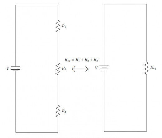
So we know how to replace multiple resistors in series with a single resistor. We can use Ohm's Law to calculate the current in this equivalent circuit, and the current in the simplified circuit is the same current that flows through the series circuit, namely I = V / Req = V / ( R1 + R2 + ... + Rn).
We can use Ohm's Law yet again to find the voltage drop across each of the series resistors now that we have an equation for the current. Remember that given current I and resistance Rj we can calculate the voltage Vj across that resistor Rjas Vj = I * Rj . Substitute the above equation for current I and you get Vj = ( V / (R1 + R2 + ... + Rn )) * Rj, where V is the source voltage. We can rearrange this equation to the following form: Vj = V * ( Rj / Req ), where Req is the sum of all the series resistors. In other words, to find the voltage across one of the series resistors, multiply the source voltage by that resistor divided by the sum of all the series resistors.
An Example Circuit
Let's build and test a real circuit and compare the expected current and voltages to the measured values.
Using the schematic of the series circuit above, for V we can use a 1.5 V AA battery, and for resistors R1, R2, and R3, we can use 1.2 kΩ, 2.7 kΩ, and 4.7 kΩ resistors. This produces the circuit as shown below:
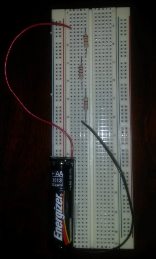
We can use a multimeter to check the voltages, currents, and resistances of all the parts of the circuit. Shown below is a table of the nominal/calculated values and their actually measured counterparts.
Table of Circuit Values
Element
| Calculated/Nominal Value
| Measured Value
|
|---|---|---|
V
| 1.5 V
| 1.40 V
|
R1
| 1.2 kΩ
| 1.18 kΩ
|
R2
| 2.7 kΩ
| 2.68 kΩ
|
R3
| 4.7 kΩ
| 4.65 kΩ
|
Req / RTotal
| 8.6 kΩ
| 8.50 kΩ
|
I
| 0.17 mA
| 0.164 mA
|
VR1
| 0.20 V
| 0.194 V
|
VR2
| 0.50 V
| 0.440 V
|
VR3
| 0.80 V
| 0.760 V
|
The measured values are pretty close to the calculated values. I encourage you to build a similar circuit with other resistance values, calculate what the voltages across the resistors should be, and measure them yourself to confirm the discussed equations.
In the next Hub, I'll discuss parallel resistive circuits. Thanks for reading!


