Ideal power transformer

Session 10
Contents
10.1 E.M.F. Equation of a transformer:
10.2 Wave form representation of flux induced E.M.F. and applied voltage:
10.3 Ideal transformer on no load:
Aim
To discuss and obtain the properties of an Ideal power transformer.
Specific objectives:
At the end of this lesson you should be able to –
- Derive expressions for the induced e.m.f. on both windings of an ideal power transformer.
- Define the properties of an ideal power transformer.
- Draw the phasor diagram of an ideal power transformer with load and without load.
Introduction:
In your last lesson, you have identified the power transformers and their necessities. With the information that you have got about transformers, if I define a transformer in the following manner, you would agree with me.
“A transformer is a static electromagnetic device designed for the transformation of one alternating current system into another one of the same frequency but with other characteristics voltage and current in particular.”
You also have studied the principle of operation of an ideal power transformer and obtained one of the basic properties.
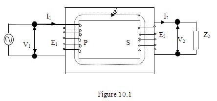
(i.e.) For the arrangement shown in Fig 10.1. You will have,
V1 / V2 = E1 / E2 = N1/N2, Where N1 and N2 are the number of turns in P and S coils respectively.
Now we will discuss it further and obtain the other properties also.
10.1 E.M.F. Equation of a transformer:
Look at Fig.10.1. The coil P is supplied by an alternating source. Hence an alternating flux will be set up in the core.
Let us say that this flux is donated by f = fm sin wt. As you know fm is the peak flux and w is the angular frequency.
As we found earlier, this flux will link the coil P and coil S and hence an e.m.f. will be induced. Consider the coil P; by Farrady’s law and Lenz’s Law. Induced e.m.f. per turn (say e,)
e = -df/dt
= -d (fm sin wt) / dt
= -fm w cos wt
= -fm w sin (p/2 - wt)
= fm w sin (wt-p/2)
If fm.w = em, then
e1 = em sin (wt-p/2)
If coil P has N1 turns, then the total e.m.f. induced = N1e1
= N1.em sin (wt-p/2)
As you know the r.m.s. value of this induced e.m.f. can be obtained by dividing the peak value by.
Let E1 be the r.m.s. value of the induced e.m.f. in coil P.
but w = 2pf
(i.e.) E1= 4.44 fm f N1 volts
Question:
Could you find an expression for the induced e.m.f. in coil S?
Answer:
You might get the expression easily if you remember your work under section 9.1 of session.
If the whole of the flux produced by coil P passes through coil S, (i.e) if there is no flux leakage, the e.m.f. induced per turn will be equal to that of the coil P.
(i.e.) Induced e.m.f at coil S per turn (say e2)
= -df/dt
= -d (fm sin wt) / dt
e2 = fm .w sin (wt-p/2)
= em sin (wt-p/2)
If N2 is the number of turns in coil S, then the total e.m.f. induced will be N2.e2.
(i.e.) Total e.m.f. induced in coil S = N2em sin (wt-p/2)
Let the r.m.s. value of the e.m.f is E2.
= 4.44 fm f N2
For coil P,
Induced e.m.f. = E1 = 4.44 fm f N1
For coil S,
Induced e.m.f. = E2 = 4.44 fm f N2
Therefore E1 / E2 = N1 / N2
If the winding resistance of coil P and S are negligible, then the voltage appearing across the terminals of coil S is the same as its induced e.m.f.
(i.e.) E2 = V2
Similarly if the resistance of coil P is also negligible, the supply voltage V1 is equal in magnitude to the induced e.m.f. in coil P and they will oppose each other.
(i.e) V1 = E1
Therefore
E1 / E2 = V1 / V2 = N1 / N2
N1 / N2 = a, where ‘a’ is known as the transformation ratio.
(i.e.) when the voltage V1 is applied across the coil P, the coil S gives the supply, at a potential V2 to the load.
The coil P is known as the primary winding and coil S is known as secondary winding. This action is known as transformer action.
10.2 Wave form representation of flux induced E.M.F. and applied voltage:
You have studies in the previous section that when an alternating flux, f = fm sin wt is set up in the core, the induced e.m.f. per turn will be em sin(wt-p/2).
Question
VV
Could you draw the forms of flux-induced e.m.f. and the applied voltage for an ideal transformer, on the same diagram?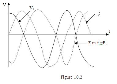
Answer:
The induced e.m.f. should lag the flux by 900 as indicated by the expressions.
By Lenz’s law, the applied voltage should be opposite to the induced e.m.f. Therefore it should lead the flux by 900
Question:
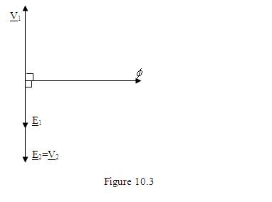
Draw the phasor representations of flux, induced e.m.f. and the applied voltage.
Answer:
As you found in the last section, the induced e.m.f. lags the flux in the core.
Take the flux as the reference phasor.
(i.e) f = fÐ00
Since the induced e.m.f. lags by 900
E1 = E1 Ð-900
and E2 = E2 Ð-900
By lenz’s law the applied voltage is opposed by the induced e.m.f.
Therefore V1 = V1Ð900
When the secondary winding resistance is negligible,
E2 = V2 = V2Ð-900
10.3 Ideal transformer on no load:
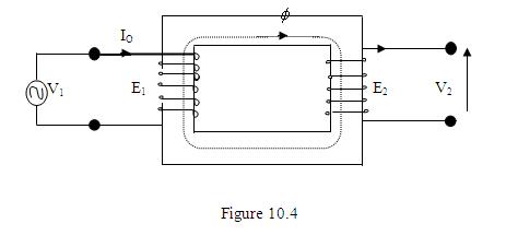
Let I0 be the primary current when the secondary is open circuited.
N1 – number of turns in the primary
N2 – number of turns in the secondary
If you could remember your magnetic circuit theory, you will be able to get an expression for the no-load current I0. It may be written that
f = N1I0 / S1
Where S1 is the reluctance of the magnetic circuit.
(i.e) I0 = S1f / N1
If the instantaneous value of I0 is i0 then
I0 = (S1/N1) fm sinwt
This will be in-phase with the flux.
Therefore the phasor diagram will be as follows:
![ROCKSTONE POWER 2000 Watt Voltage Converter Transformer - Heavy Duty Step Up/Down AC 110V/120V/220V/240V Power Converter - Circuit Breaker Protection – DC 5V USB Port - CE Certified [3-Year Warranty]](https://m.media-amazon.com/images/I/41ACqRbZQFL._SL160_.jpg)


