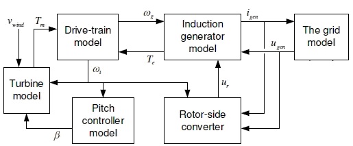
Modeling a wind turbine in MATLAB

INTRODUCTION
Following the fact that every country in the world should use renewable energy sources in their transmission power systems, this case study came as result of the initial project of implementing renewable energy sources, or to be more specific, wind power energy into the electrical power system of Republic of Macedonia. In the initial project, authorities have planned to implement DFIG (Double Fed Induction Generator), because of the fact that it will drastically decrease the costs for invertors, it will enable control of the torque and as last, it will increase the efficiency of wind extraction. Motivated by the advantages that DFIG offers regarding other types of wind turbines, this study will explain some of the dynamics that occur in cases when there are active short circuits on 110 kV buses and in cases when the wind speed changes immediately. The model of DFIG wind turbine will be described accompanied by the mathematical model. Dynamic simulations have been developed in MATLAB, and will be presented in the study. Because the turbine is a set of many sub models that are working as one, proper explanation for every sub model will be given. The results of the simulations are the most important thing that engineers will use in order to increase the reliability of the power system and turbine. Thanks to the unlimited possibilities of MATLAB, modeling the wind turbine was easy.
Wind turbine model description
Fig 1. Model of DFIG wind turbine
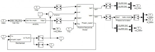
MATLAB model of the generator
From the electrical machines theory, we can state that DFIG is actually an induction generator. It would be of interest to everyone to describe the basics of the DFIG according to electrical machines theory. The generator is modeled according the dq component system. As description of the further explanation of the generator modeling, the MATLAB SIMULINK model of the generator is presented on Fig.2.
Fig. 2 MATLAB SIMULINK model of DFIG
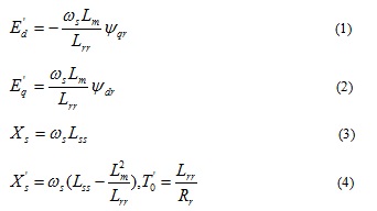
At start, for the DFIG model a brief mathematical explanation must be provided. However, to do that, the equivalent circuit of a DFIG must be presented, and in this study it is presented on Fig. 3.
Fig. 3 Equivalent circuit of DFIG
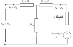
The mathematical model of the equivalent circuit must needs mathematical constants like,
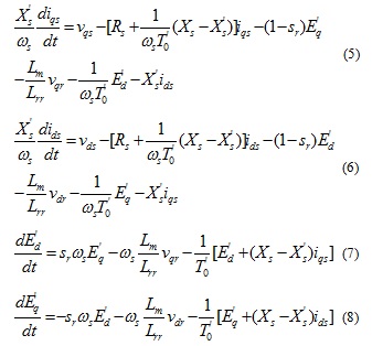
Model of the drive train
The drive train is the mechanical part of the system that consists of gearbox, shafts, turbine and other important mechanical parts. In this study, the two mass drive train model is used and is presented on Fig. 4. The two mass drive train model is used because of the fact that the turbine model is represented as one mass, while the generator is the other mass. Both masses are connected with a mechanical shaft that possesses certain damping and stiffness value. In the expression, T represents the torque, Ω is the angular speed and J is the inertia moment. In the expressions, subscripts t and g represent the generator and turbine side respectively.
Fig. 4 Two mass drive train model

Rotor side controller
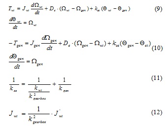
The main purpose of using the rotor side controller is to measure and control the voltage and energy on the output of the turbine. The logic that is used is PI controllers. By using PI controllers, the overall energy is added to the overall loss of energy, and that sum is compared to the reference value from the characteristic. When the controller works in voltage regulation mode, the PI control is performed through the UI characteristic. The PI controller is actually used to decrease the error of the power to zero. The simplified block diagram of the rotor side converter is presented on Fig. 5.
Fig. 5 Rotor side controller
SIMULATION
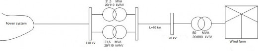
In this study case we have made a simplified MATLAB Simulink model of the transmission power system of Macedonia. In that power system there is a wind farm of 50 MW that has to be installed. The number of used wind turbines is 25, each one of them with installed power of 2 MW. All turbines are DFIG. In the initial MATLAB model of the study case, we implemented all 25 turbines in one system, and thus we received one system with 50 MW of power. A block diagram of the model used in this study case is presented on Fig. 6.
Fig. 6 Simplified model
Two tests have been performed. The first test was made under short circuit on the 110 kV bus near the wind farm, or to be more specific, on the place where the wind farm is connected to the transmission power system. At the second test we assumed that on the wind farm there was a sudden change on the wind speed. The turbine works in two modes. The first mode is VAR Regulation while the other mode is the Voltage regulation. It is in everyone’s interest to perform simulations under these two working modes. At first we will start by assuming that we have single phase short circuit on the 110 kV bus.
As first test we decided that we will use the case where the wind farm works in Voltage regulation mode. The single phase short circuit starts at 5 sec and lasts until 5.18 sec. For this purpose we present the following screenshots for the Network parameters and Turbine parameters, accordingly. As first diagram we will present the Network parameters on Fig. 7, while the Turbine parameters are presented on Fig. 8.
Fig. 7 Network parameters
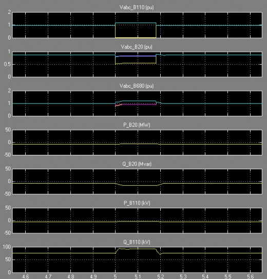
Fig. 8 Turbine parameters
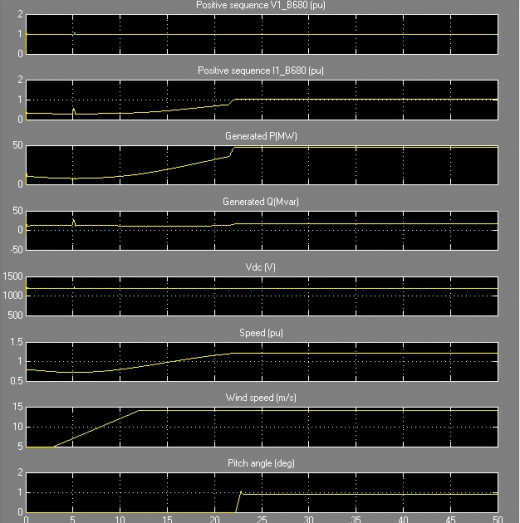
As it is presented in Fig. 7, on the 5thsecond there is an active short circuit on the 110 kV buses. During the short circuit period we see that the voltage on one phase on the 110 kV bus drops to 0 and lasts during the short circuit period. It is in our interest to track all the parameters in the wind turbine. We can see from Fig. 8 that the voltage at the wind turbine terminals during the short circuit drops to 0.97. The turbine protection system is set up to react in cases when the voltage drops under 0.95 pu for time greater than 0.1 seconds. The wind farm continues to work and gives full power in the transmission system. In conclusion we can state that the short circuit didn’t affect the work of the turbines. In the second working mode which is called VAR regulation mode, the wind turbine trips and stops working from the 5th second.
In the second experiment we assume that the wind turbine worked in Voltage regulation mode. The turbine works during the whole period that is given in the simulation parameters. On Fig. 9 we present the Network parameters and the results from the simulation.
Fig. 9 Network parameters
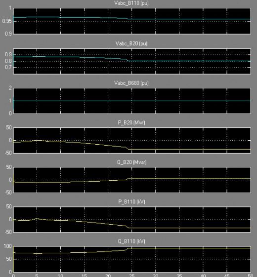
Fig. 10 Turbine parameters
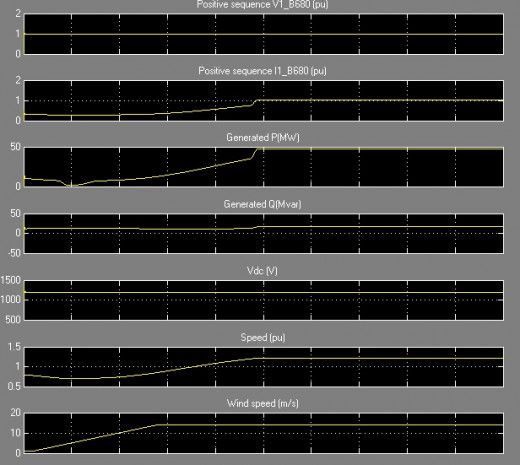
As it can be seen from the simulation results in Fig. 9 and Fig. 10, in this mode, the system continues to work and generates power into the transmission power system. From Fig. 10 that represents the turbine parameters it can be seen that the wind speed increases to 14 m/s starting from the 3rd second of the simulation period. The pitch angle increases up to 1.2 degrees in order to control the mechanical power of the turbine. It is a protection algorithm which is used in the protection of the wind turbine. In the VAR regulation mode, the wind turbine trips and doesn’t insert energy into the power system, because of the fact that the protection which is set up to disconnect the turbine from the network in case the voltage on the output of the turbine drops under 0.95 pu, reacts and disconnects the turbine from the network.
CONCLUSIONS
From the simulation results shown in the previous section of the article a very useful conclusion can be drawn. Because Republic of Macedonia is in constant need of electrical energy, our proposal would be to implement the wind turbines into the system, and they should work in Voltage regulation mode. The place where the turbines will be installed is windy, and if the VAR regulation mode is used, then the system won’t have great benefit of them. The Voltage regulation mode is more tolerant unlike the other mode, where the turbine trips and disconnects from the network.


")


