My Experiences With Microcontrollers - Part 2
Introduction
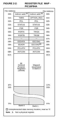
The data memory is divided into RAM Data Memory and Data EEPROM Memory. RAM is used to store variables and data, which are deleted when the power goes out. The EEPROM memory is a small area of non-volatile read and writes data memory and it helps us to recover data information when there is no power supply.
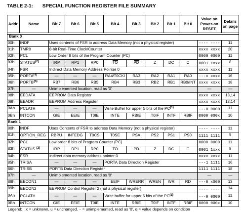
Special Function Records SFR: Each of these registers fulfills a special purpose in the control of the microcontroller.
General Purpose Registers GPR: These are general purpose registers that can be used to store the temporary data of the program that is being executed.
The data memory has two memory banks in PIC16F84A: Bank 0 and Bank 1. SFR records are grouped between addresses 00h to 0Bh for Bank 0 and between addresses 80h and up to 8Bh for Bank 1. Some of the SFR records are duplicated in the same direction in the two banks, with the purpose of simplifying their access.
Configuration Register
The configuration of the microcontroller is necessary to program it since by default all registers are at 1. Its configuration in PIC16F84A is the following:
CP Registration
It helps us to enable the protection code
If CP = 0, if the protection code is enabled
If CP = 1, the protection code is not enabled
PWRTE registration
It helps us to enable the Timer
If PWRTE = 0, if the Timer is enabled
If PWRTE = 1, the Timer is not enabled
WDTE registration
It helps us to enable the Watchdog Timer
If WDTE = 0, the WDTE is not enabled
If WDTE = 1, if WDTE is enabled
Records FOSC1: FOSC0
It helps us to select the type of oscillator
00 = LP oscillator
01 = XT oscillator
10 = HS oscillator
11 = RC oscillator
Statur Register
In this record we will find the last operation performed and the most important settings of your records are:
The RP0 record serves to select the Data Bank.
If RP0 = 0, Bank 0 was selected
In Assembly Language we would write: bcf STATUS, RP0
If RP0 = 1, Bank 1 was selected
In Assembly Language we would write: bsf STATUS, RP0
Registration / TO
If / TO = 0, if the Watchdog overflows
If / TO = 1, the Watchdog does not overflow
Registration / PD
If / PD = 0, the microcontroller is in low power or sleep mode
If / PD = 1, the microcontroller in power mode or in CLRWDT
Registration Z
If / Z = 0, the last arithmetic or logical operation is different from zero
If / Z = 1, the last arithmetic or logical operation is zero
Option Register
This registry governs the Timer and the configurations of its most important registers are:
TOCS registration
Configuration of the TMR0
If TOCS = 0, the TMR0 is used as a Timer
If TOCS = 1, the TMR0 is used as an Accountant
TOSE registration
Selection of the flank to be increased
If TOSE = 0, rising edge
If TOSE = 1, falling edge
PSA registration
Assignment of the Frequency Divider or Prescaler
If PSA = 0, assignment to TMR0
If PSA = 1, assignment to Watchdog
Records PS2 PS1 PS0
Prescaler configuration.
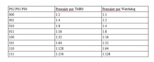
In the next chapter we are going to see the INTCON record and some code examples with Timers.


