My Experiences With Microcontrollers - Part 3


Introduction
The INTCON register is the register that controls the interrupts and contains 8 bits that control the flag flags of the states of the interrupts and others as permission bits so that the interruptions can be made. Next, we explain what each of these registers is for and then we will give some examples.
GIE Register
Global Interruption
If GIE = 0, does not authorize the interruption
If GIE = 1, if you authorize the interruption
EEIE Register
EEPROM
If EEIE = 0, registration is disabled
If EEIE = 1, registration is enabled
T0IE Register
Timer overflow
If T0IE = 0, registration is disabled
If T0IE = 1, registration is enabled
INTE Register
Interruption configuration RB0 / INT
If INTE = 0, registration is disabled
If INTE = 1, registration is enabled
RBIE Register
Configuration of the interruption RB7: RB4
If RBIE = 0, registration is disabled
If RBIE = 1, registration is enabled
T0IF Register
Timer Interruption Flag TMR0
If T0IF = 0, the record has not been overflowed
If T0If = 1, the registration overflowed
INTF Register
Signage or indicator of the INTF record
If INTF = 0, it indicates that there is no interruption in RB0 / INT
If INTF = 1, it indicates that if there is an interruption in RB0 / INT
RBIF Register
Signage or indicator of the RBIF record
If RBIF = 0, it indicates that there is no interruption in RB4: RB7
If RBIF = 1, it indicates that if there is an interruption in RB4: RB7
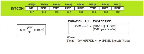
1) Example of Timer with PIC16F84A
Calculate the TMR0 for a time of 250 us, prescaler of 2 and a square wave that leaves by the RB3 port. In this port we can place a speaker to listen to the sound produced.
For 2 kHz each half period lasts 250 us
250 us = 1x2 x (256 - Load_TMR0)
Load_TMR0 = 131
256-131 = 125 pulses before overflowing
To configure the Timer0 with prescaler 2, the OPTION register must be loaded with b'00000000 'as we can check in the second part of this tutorial.
To obtain the square wave with a half-period of 250 us, we must do:
EQU d'256'-d'131 '
As the PIC works at a frequency of 4 MHz, the TMR0 evolves every microsecond.
To achieve a delay of 250 μs with a prescaler of 2 the TMR0 must count 125 impulses. Effectively: 1 μs x 125 x 2 = 250 μs.
Assembler code
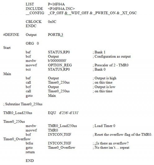
2) Example of T0I interruption with PIC16F84A
Calculate the TMR0 for a time of 100 us, prescaler of 1 and a square wave that leaves by the port RB3. In this port we can place a speaker to listen to the sound produced.
In a square wave of 5 kHz each half period lasts 100 us
100 us = 1x1 x (256 - Load_TMR0)
Load_TMR0 = 156
256-156 = 100 pulses before overflowing
To configure without prescaler for the Timer0 and assign it to the Watchdog, the OPTION register must be loaded with b'00001000 'as we can check in the second part of this tutorial.
To obtain the square wave with a half-period of 100 us, we must do:
EQU d'256'-d'100 '
As the PIC works at a frequency of 4 MHz, the TMR0 evolves every microsecond.
To achieve a delay of 100 μs with a prescaler of 1, the TMR0 must count 100 pulses. Effectively: 1 μs x 100 x 1 = 100 μs.
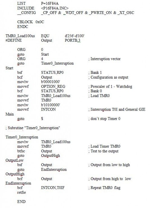
We ensure the interruption T0I and the GIE if we load in the INTCON register the value: b'10100000 '
Finally we replace the TMR0 flag with: bcf INTCON, T0IF
Assembler code
")