Step by Step Guide to Repair Your Ethernet Network Cable

In modern times, being online is the most preferred way of interaction. Right from personal things like talking with friends to professional tasks such as running a business or having a conference meeting with an offshore client To have a robust and always-on network infrastructure is indispensable. Ethernet cables are the backbone of a well implemented LAN (Local Area Network) as it connects individual devices with the rest of the world either directly or indirectly (in case of wireless networks). Even though ethernet cables are built to be durable, they are prone to deterioration from bends, kinks or even from daily use such as twists, knots or broken peripherals.
Assuming a benefit of the doubt, this article will focus on the different steps involved in patching an ethernet network cable which can be replicated to repair your network cable (from the 2nd step).
Tools Required
Before we jump in head-first into building your ethernet cable network it is important that you have all necessary tools within an arm’s reach.
")


")
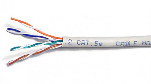
Step 1: Identify your network cable type
While all ethernet cables look similar, there is a minor factor that separates the cables into 3 categories.
- CAT 5e
- CAT 6
- CAT 6a
The differentiating factor is the number of twist per inch and the ability to carry 1 Gbits (CAT 5e) or 10 Gbits (CAT 6 or 6a) across a segment length of 200 meters. CAT 5e manages to meet the criteria for frequencies up to 100 MHz, CAT 6 manages to carry frequencies up to 250 MHz and CAT 6a does so till 500 MHz. The higher twists per inch mean lower interferences and higher the cost of the cable. The cable category is mentioned on the outer sleeve of the cable and can be clearly distinguished.
Step 2: Prepare your cable
Now that you have chosen the cable, it is now time to prepare your cable for crimping. Crimping is an industrial term for terminating the cable with an 8P8C (8 Point 8 Contact) modular connector. Quite often it is mistaken as RJ45 (Radio Jack with pin 4 and 5 wired). Contrarily in case of ethernet cables, the pin 4 and 5 are left unwired and data transfer happens between remaining pairs of pins i.e. pins pair 1 and 2 for data transmission and pin pair 3 and 6 for data reception.
Step 2a: Remove external sleeve
Most crimping tools are equipped with a wire stripping blade which can be used to make a clean cut around the ethernet cable outer sleeve. In case you are using plug boots to cover the 8P8C connectors, this is a good time to insert them into the cable. Use the crimping tool to make a cut around 1.5 cms from the end. You shall see 4 pairs of twisted wires surrounded by either an aluminum shielding (for shield twisted pair cables) or white fibers. The white fibers are to provide strength and bulk to the core. You can cut them away to reduce obstructions.
Step 2b: Arrange the wires in the correct order
As you can see, you shall have 4 pairs of twisted wires with different colors on their individual sleeves. The color scheme is as follows:
Wire Number
| Color on the sleeve
|
|---|---|
1
| White with Orange stripes
|
2
| Orange
|
3
| White with Green stripes
|
4
| Blue
|
5
| White with Blue stripes
|
6
| Green
|
7
| White with Brown stripes
|
8
| Brown
|
Now based on the wiring standards followed in your country, the wire arrangement has a minor change. For countries following T568A wiring standards, the pin 1 & 2 are connected to the white-green wire pair and pin 3 & 6 are connected to white-orange wire pair. Those following T568B wiring standards, the wire placements are interchanged.
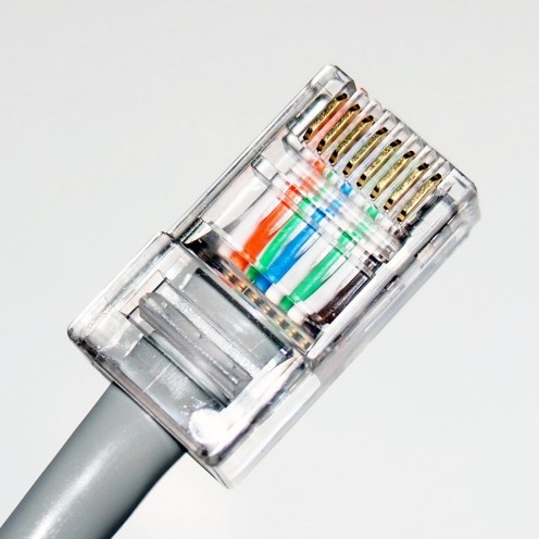
Step 3: Insert wires to the 8P8C connector
As stated earlier, depending on the particular wiring standard, the pin 1 will either have a white-green or white-orange wire. But how to determine which is the pin 1? Ideally, the pin 1 in an RJ45 connector is the one on the far left, when the connector’s contacts are facing up. When you push the wires into the connector, there are plastic paths to help guide individual wires into separate contact.
If you had properly cut the sleeve of the outer wire, there should be enough sleeve to be held by the groove at the bottom of the 8P8C connector. If done correctly, your cable should look like the image below.
Step 4: Use the crimping tool
Once you have aligned the wires perfectly inside the connector, use the crimping tool to apply pressure on the gold connections and the wedge at the bottom to secure the cable with the 8P8C connector. A couple of firm squeezes would do the trick. Pull up the plug boots to protect the cable from damages owing to unnecessary bends. Repeat with the other end of the cable to create an Ethernet network cable.
Step 5: Test your connection
You can use a cable tester to confirm continuity or directly plug into the desired system to test the connections.
Step 6: Celebrate
Congratulations!!! You have progressed from cursing the internet gods for no internet to creating your own network cable. As the proverb goes, “Give a man a fish and you feed him for a day; Teach a man to fish and you feed him for a lifetime”. Now go forth and put this knowledge to good use.
© 2019 Hiren Pancholi


