- HubPages»
- Technology»
- Computers & Software»
- Computer Software
database terminology


Like any other part of computing, database management is full of buzz words, Here we are going to review and explain them. My intention here is to demystify buzz words, so that they can become part of a DBA’s (database administrator’s) toolkit rather than just part of the vocabulary. The references to glossary terms are tongue-in-cheek.
UML
Let’s start with Unified Modeling Language (UML) for Object-Oriented Database Architecture. These just the recently fashionable terms for things that have been around for quite a while. UML isn’t even a language – it’s a charting mechanism (glossary term 1). Many of us have used basic flow chart methodology to do more than flowcharts (which diagram programming projects) – we’ve used them to chart processes, data flow, people flow…you name it. The UML is simply a method chosen by the OMG (Object Management Group) as a standard – much like HTML is a standard for the World Wide Web. OMG claims that this will be a better communication medium between business-minded clients and technically-minded programmers. Well, folks – a layman can understand a basic flow chart – you need training not only to use UML but to understand it! Nonetheless it’s a handy buzz word for resumes and job interviews, so we will look into it.
Formal UML has nine basic modeling diagrams. Glossary term 2 – “modeling” = designing or blueprinting. And actually, these modeling methodologies can be applied not only to programming, but to bank activity flow, building houses, systems analysis, needs analysis, just about any project. We will look ever so slightly into 6 of these diagrams.
Use case diagrams
Borland describes Use Case as a diagram that describes what a system does from the standpoint of an external visitor, defining what a system does rather than how. ‘Actors’ (glossary term 3) ‘communicate’ (glossary term 4) with a ‘use case’ (glossary term 5), or a system or use of a system. Since we are going into database management systems, we will concentrate on examples in the software development business. Let’s say you are working on a system for a restaurant. You need to identify all the systems and users involved to see the relationships between people, computers, manual and automated processes. In diagram form:
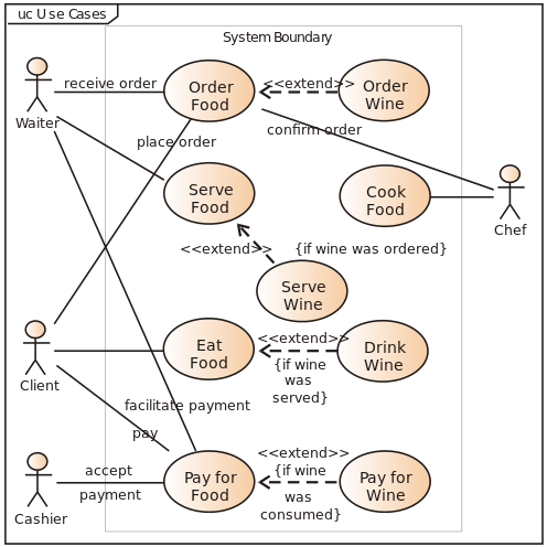
Actor is usually a stick figure
Line is the communication association
Oval = use case
In this simplified form it seems worthless. But if you look at all related use cases, you ended up with a Use Case Diagram:
ACTOR
| USE CASE
| ACTOR
|
|---|---|---|
patron
| order food
| waiter
|
patron
| eat food
| |
patron
| pay for food
| cashier - accept payment
|
waiter
| order to/from chef
| chef - prepare food
|
a partial analysis of the use case diagram above
As you see, the Use Case may be a program, a person, a situation or an object. Use case diagrams are helpful for determining requirements (needs analysis), reviewing with a client the situations that require an application to be developed, and for generating test cases.
The Use Case diagram has a good place in development - if it's used properly, and thoroughly. First, it's a way to verify that your analysis of the client's situation is correct, because it's simple enough for the client to understand yet complete enough for the developer to get a grip on the data flow, what can be done, where manual procedures can be replaced by automated systems, and how redundancies can be eliminated. So it's a great sales tool. I like to show the prospective client before and after diagrams – to show how much manual effort can be converted to automated work.
Class Diagrams
A class (glossary term 6) is, per Borland, an overview of a system by showing its classes and relationships between classes. This describes which classes interact, but does not actually show the consequences of interaction. A class is diagramed as a rectangle split into three sections. The top section is the name of the class; the middle section is the attributes that class possesses, and the bottom section is the operations that class can perform.
Let’s say we are going to develop an MIS for a camera store. The class diagram of the store would be :
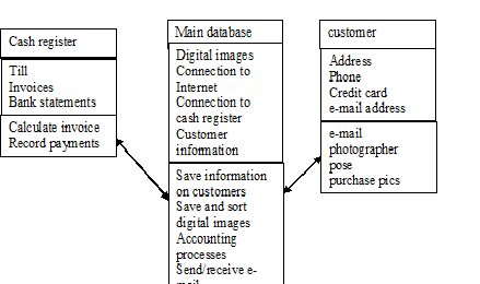
There are 3 kinds of relationships possible in a class diagram:
- association – an existing relationship between two classes – a line linking two classes
- aggregation – one class belongs to a collection – designated by a line with a diamond at the collection end
- generalization – one class is a subclass of another – denoted with a line with a triangle at the superclass (parent) end
(glossary terms 7,8 and 9)
Interaction diagrams
Interaction diagrams show the effect one class has on another. Interaction diagrams come in two types:
- sequence diagrams – these show how operations are carried out, along a time line. If you’ve ever seen a Gantt chart for a project, you have seen a type of sequence diagram.
- collaboration diagrams – these are similar to sequence diagrams but they focus on the roles of the classes rather than the time line.
(glossary terms 10, 11 and 12)
State diagram
these focus on the changes of a class’ state as other classes affect it. (glossary term 13)
Activity diagrams
These focus on the activities involved in a single process. This is what you think of when you do a flow chart of a particular module. (glossary term 14)
I am currently qualifying a network. The original templates for diagramming the network were done for a small site, by a Visio specialist who had no technical knowledge. The result was a stringent template with no practical use at all. I have now, after a year of wrangling, gotten them to revamp the template to make it of use in redlining and troubleshooting.
Why am I numbering the ‘glossary terms’? Because I think some people get so involved in names and structures that they forget the practical usage of the thing. Glossary terms are just buzz words that might come in handy and are generally accepted.
Object-Oriented Database Architecture
Again, this gets to the point of absurdity. The concept was first introduced as Object Oriented Programming Structure – better known to many of us as OOPS, and well-named. Again it is an attempt to redefine the wheel – the thing still goes around, no matter what you call it. The advantage of OO (Object Orientation) is for the use of CASE stations – many people can work on the development of a single application at once, guided by the diagrams of the objects. The other advantage is in database management, simply because DBMSs (Database Management Systems) now use these terms on an almost universal scale, so if you are working with one, you can understand the references. I got involved with OO when studying AI (Artificial Intelligence) because the AI languages (such as ADA) use the class (object) system in their architecture. Each object has inheritance – the ability to ‘inherit’ characteristics from a super class. For instance you may have a class called DOG, which has the attributes 4-legged, tail, 2 ears, fur. Then you create a ‘child’ class called DALMATIAN, which inherits all the dog attributes plus the attribute black-spots-on-white, short hair, and large-size.
Object-Oriented database architecture involves:
- Object-Oriented technology:
- Encapsulation
- Attributes
- Methods
- Inheritance
- Polymorphism
- Transcience
- Persistence
A quick overview of the object-oriented glossary:
table - A database is like a file cabinet. The drawers of the cabinet would be the tables – collections of records in file folders. Each record is made up of field of various data types – these would correlate with the headings you might put on a spreadsheet. Each table can have one key field, whose entries cannot be blank or duplicated in that field. Each table can also have one or more indexed fields, for quick reference. Any time two tables have the same field, a relationship can be built between the tables at that field.
If you have an indexed field and you do a search on that field, the database does not load up the entire record to find the correct record; it only loads up the indexed field(s); when the entry is found, the database loads up the rest of the record. This saves time – unless you index a lot of fields in one table.
Oracle works on a similar basis, but each field is its own table, plus an index. When it searches a field (table) and finds what it’s seeking, Oracle then loads up only the tables (fields) requested that correlate with the index.
Query – an object which combines and selects information from table objects
Form – an object which displays data from table or query objects
Report – a printable object display of data; can be dynamic or static
Macro – an object which collects a series of objects and executes them in a chronological order