Switch With dsPIC30F4013
Introduction
DsPIC is a generic name that is used to refer to digital signal controllers (DSC) that has designed "Microchip" to facilitate users, transition to the field of applications of digital signal processes. They are the first PICs with inherent data bus of 16 bits. They incorporate all the possibilities of the previous PICs and add several DSP operations implemented in hardware, such as multiplication with sum of accumulator (MAC), carry inversion or multiplication 16x16 signed bits. The following features should be highlighted: Single cycle instruction set (Including multiplication); Work with a 16 bit data BUS (fixed or floating point); Incorporate a large RAM; High speed and complex algorithms (high performance); Addressing modes intended for processing; Have fast and accurate A/D converters; Are prepared to be programmed in high-level languages.

dsPIC FAMILIES
They begin to be produced on a large scale at the end of 2004, but today more than 100 models of this type of device are being commercialized, used for advanced MCU and audio applications (general purpose), and for the control of sensors, motors and Feeding systems, meeting in the following two families:
1st FAMILY: dsPIC30F Architecture and instruction set of traditional MCUs, adding the functionality and main requirements of DSPs.
2nd FAMILY: dsPIC33F Capabilities, number of peripherals and performance are enhanced, allowing access to more complex fields of application.
The most significant characteristics with dsPIC30F are the following:
21 models available
5 timers
Modes of work with low energy:
1. IDLE
2. SLEEP
Power supply from 2 to 5.5 V
Performance: MIPS at 4.5 or 5.5 V
Few Vectors of Interruption (62)
Memory EEPROM
Flash memory up to 144 KB
SRAM memory up to 8 KB
In my case I have worked with dsPIC30F2010 and dsPIC30F4013 and the main projects were the following:
- Audio Digital Signal Processing Using A dsPIC30F4013
- FIR Digital Filter With dsPIC30F2010
- PWM PID Temperature Control Wirh dsPIC30F4013
- Servo Motor + dsPIC30F2010
- Generating 3 PWM and 4 PWM signals With dsPIC30F2010
- Measuring Phase With a dsPIC30F4013
Example: Switch With dsPIC40F4013
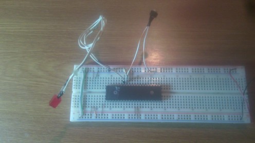
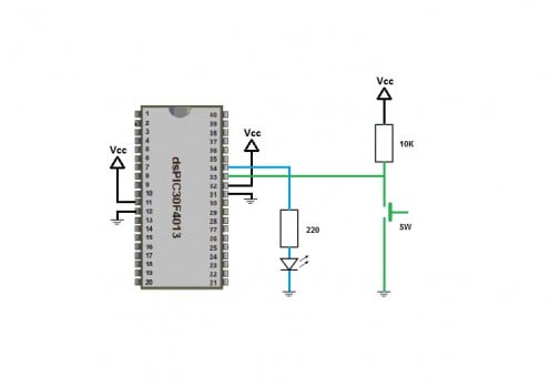
Here is a simple application where we use a dsPIC30F4013 as a switch for turning on and off an LED. This test we can see it in the following image and the following video.

Download Code
Links with similar content:
- PulseIn and Time with Arduino
Use of pulseIn and the Time library to measure time with Arduino - My Favorite Projects With PICC
Show my experiences with the PIC16F887 using the PICC compiler. - My Microrobot Genius
Show my experiences developing a Microrobot. - My Automation Home with Arduino
Show my experiences developing an Automation Home with Arduino and App Inventor 2. - Led Matrix With Arduino UNO
Show the use of a LED Matrix with Arduino - My Weather Station With Arduino
Show my experiences developing weather stations - My Favorite Projects with Arduino UNO and Mega2560
Projects realized with the Arduino UNO and Mega 2560 boards - My Projects with Mega2560
Projects realized with the Mega 2560 board
© 2017 Guillermo Perez Guillen


